Mobile Com puting Chapter 4: Wireless Telecommunication Systems
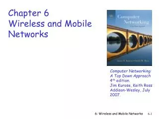
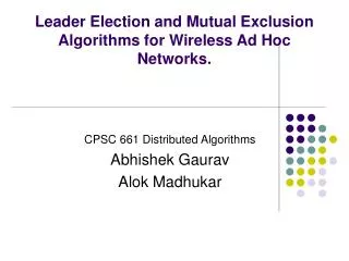
Mobile Com puting Chapter 4: Wireless Telecommunication Systems. Market GSM Overview Services Sub-systems Components. DECT TETRA UMTS/IMT-2000. Mobile phone subscribers worldwide. 1200. 1000. GSM total. 800. TDMA total. CDMA total. 600. PDC total. Subscribers [million].

Mobile Com puting Chapter 4: Wireless Telecommunication Systems
E N D
Presentation Transcript
Mobile ComputingChapter 4: Wireless Telecommunication Systems Market GSM Overview Services Sub-systems Components • DECT • TETRA • UMTS/IMT-2000 4.1
Mobile phone subscribers worldwide 1200 1000 GSM total 800 TDMA total CDMA total 600 PDC total Subscribers [million] Analogue total Total wireless 400 Prediction (1998) 200 0 year 1996 1997 1998 1999 2000 2001 2002 4.2
Development of mobile telecommunication systems CT0/1 FDMA AMPS CT2 NMT IMT-FT DECT IS-136 TDMA D-AMPS EDGE IMT-SC IS-136HS UWC-136 TDMA GSM GPRS PDC IMT-DS UTRA FDD / W-CDMA IMT-TC UTRA TDD / TD-CDMA IMT-TC TD-SCDMA CDMA IS-95 cdmaOne IMT-MC cdma2000 1X EV-DO cdma2000 1X 1X EV-DV (3X) 2G 3G 1G 2.5G 4.3
GSM: Overview • GSM • formerly: Groupe Spéciale Mobile (founded 1982) • now: Global System for Mobile Communication • Pan-European standard (ETSI, European Telecommunications Standardisation Institute) • simultaneous introduction of essential services in three phases (1991, 1994, 1996) by the European telecommunication administrations (Germany: D1 and D2) seamless roaming within Europe possible • today many providers all over the world use GSM (more than 184 countries in Asia, Africa, Europe, Australia, America) • more than 747 million subscribers • more than 70% of all digital mobile phones use GSM • over 10 billion SMS per month in Germany, > 360 billion/year worldwide 4.4
Performance characteristics of GSM (wrt. analog sys.) • Communication • mobile, wireless communication; support for voice and data services • Total mobility • international access, chip-card enables use of access points of different providers • Worldwide connectivity • one number, the network handles localization • High capacity • better frequency efficiency, smaller cells, more customers per cell • High transmission quality • high audio quality and reliability for wireless, uninterrupted phone calls at higher speeds (e.g., from cars, trains) • Security functions • access control, authentication via chip-card and PIN 4.5
Disadvantages of GSM • There is no perfect system!! • no end-to-end encryption of user data • no full ISDN bandwidth of 64 kbit/s to the user, no transparent B-channel • reduced concentration while driving • electromagnetic radiation • abuse of private data possible • roaming profiles accessible • high complexity of the system • several incompatibilities within the GSM standards 4.6
GSM: Mobile Services • GSM offers • several types of connections • voice connections, data connections, short message service • multi-service options (combination of basic services) • Three service domains • Bearer Services • Telematic Services • Supplementary Services bearer services MS GSM-PLMN transit network (PSTN, ISDN) source/ destination network TE MT TE R, S Um (U, S, R) tele services 4.7
Bearer Services • Telecommunication services to transfer data between access points • Specification of services up to the terminal interface (OSI layers 1-3) • Different data rates for voice and data (original standard) • data service (circuit switched) • synchronous: 2.4, 4.8 or 9.6 kbit/s • asynchronous: 300 - 1200 bit/s • data service (packet switched) • synchronous: 2.4, 4.8 or 9.6 kbit/s • asynchronous: 300 - 9600 bit/s • Today: data rates of approx. 50 kbit/s possible – will be covered later! 4.8
Tele Services I • Telecommunication services that enable voice communication via mobile phones • All these basic services have to obey cellular functions, security measurements etc. • Offered services • mobile telephonyprimary goal of GSM was to enable mobile telephony offering the traditional bandwidth of 3.1 kHz • Emergency numbercommon number throughout Europe (112); mandatory for all service providers; free of charge; connection with the highest priority (preemption of other connections possible) • Multinumberingseveral ISDN phone numbers per user possible 4.9
Tele Services II • Additional services • Non-Voice-Teleservices • group 3 fax • voice mailbox (implemented in the fixed network supporting the mobile terminals) • electronic mail (MHS, Message Handling System, implemented in the fixed network) • ... • Short Message Service (SMS)alphanumeric data transmission to/from the mobile terminal using the signaling channel, thus allowing simultaneous use of basic services and SMS 4.10
Supplementary services • Services in addition to the basic services, cannot be offered stand-alone • Similar to ISDN services besides lower bandwidth due to the radio link • May differ between different service providers, countries and protocol versions • Important services • identification: forwarding of caller number • suppression of number forwarding • automatic call-back • conferencing with up to 7 participants • locking of the mobile terminal (incoming or outgoing calls) • ... 4.11
Architecture of the GSM system • GSM is a PLMN (Public Land Mobile Network) • several providers setup mobile networks following the GSM standard within each country • components • MS (mobile station) • BS (base station) • MSC (mobile switching center) • LR (location register) • subsystems • RSS (radio subsystem): covers all radio aspects • NSS (network and switching subsystem): call forwarding, handover, switching • OSS (operation subsystem): management of the network 4.12
GSM: overview OMC, EIR, AUC fixed network HLR GMSC NSS with OSS VLR MSC VLR MSC BSC BSC RSS 4.13
GSM: elements and interfaces radio cell BSS MS MS Um radio cell MS RSS BTS BTS Abis BSC BSC A MSC MSC NSS VLR VLR signaling HLR ISDN, PSTN GMSC PDN IWF O OSS EIR AUC OMC 4.14
GSM: system architecture radiosubsystem network and switching subsystem fixedpartner networks MS MS ISDNPSTN MSC Um Abis BTS BSC EIR BTS SS7 HLR VLR BTS ISDNPSTN BSC BTS MSC A IWF BSS PSPDNCSPDN 4.15
Components MS (Mobile Station) BSS (Base Station Subsystem):consisting of BTS (Base Transceiver Station):sender and receiver BSC (Base Station Controller):controlling several transceivers Interfaces Um : radio interface Abis : standardized, open interface with 16 kbit/s user channels A: standardized, open interface with 64 kbit/s user channels System architecture: radio subsystem radiosubsystem network and switchingsubsystem MS MS Um Abis BTS MSC BSC BTS A BTS MSC BSC BTS BSS 4.16
System architecture: network and switching subsystem networksubsystem fixed partnernetworks • Components • MSC (Mobile Services Switching Center): • IWF (Interworking Functions) • ISDN (Integrated Services Digital Network) • PSTN (Public Switched Telephone Network) • PSPDN (Packet Switched Public Data Net.) • CSPDN (Circuit Switched Public Data Net.) • Databases • HLR (Home Location Register) • VLR (Visitor Location Register) • EIR (Equipment Identity Register) ISDNPSTN MSC EIR SS7 HLR VLR ISDNPSTN MSC IWF PSPDNCSPDN 4.17
Radio subsystem • The Radio Subsystem (RSS) comprises the cellular mobile network up to the switching centers • Components • Base Station Subsystem (BSS): • Base Transceiver Station (BTS): radio components including sender, receiver, antenna - if directed antennas are used one BTS can cover several cells • Base Station Controller (BSC): switching between BTSs, controlling BTSs, managing of network resources, mapping of radio channels (Um) onto terrestrial channels (A interface) • BSS = BSC + sum(BTS) + interconnection • Mobile Stations (MS) 4.18
GSM: cellular network cell • use of several carrier frequencies • not the same frequency in adjoining cells • cell sizes vary from some 100 m up to 35 km depending on user density, geography, transceiver power etc. • hexagonal shape of cells is idealized (cells overlap, shapes depend on geography) • if a mobile user changes cells handover of the connection to the neighbor cell segmentation of the area into cells possible radio coverage of the cell idealized shape of the cell 4.19
Example coverage of GSM networks (www.gsmworld.com) Vodafone (GSM-900/1800) T-Mobile (GSM-900/1800) Berlin e-plus (GSM-1800) O2 (GSM-1800) 4.20
Base Transceiver Station and Base Station Controller • Tasks of a BSS are distributed over BSC and BTS • BTS comprises radio specific functions • BSC is the switching center for radio channels 4.21
Mobile station TE TA MT Um R S • Terminal for the use of GSM services • A mobile station (MS) comprises several functional groups • MT (Mobile Terminal): • offers common functions used by all services the MS offers • corresponds to the network termination (NT) of an ISDN access • end-point of the radio interface (Um) • TA (Terminal Adapter): • terminal adaptation, hides radio specific characteristics • TE (Terminal Equipment): • peripheral device of the MS, offers services to a user • does not contain GSM specific functions • SIM (Subscriber Identity Module): • personalization of the mobile terminal, stores user parameters 4.22
Network and switching subsystem • NSS is the main component of the public mobile network GSM • switching, mobility management, interconnection to other networks, system control • Components • Mobile Services Switching Center (MSC)controls all connections via a separated network to/from a mobile terminal within the domain of the MSC - several BSC can belong to a MSC • Databases (important: scalability, high capacity, low delay) • Home Location Register (HLR)central master database containing user data, permanent and semi-permanent data of all subscribers assigned to the HLR (one provider can have several HLRs) • Visitor Location Register (VLR)local database for a subset of user data, including data about all user currently in the domain of the VLR 4.23
Mobile Services Switching Center • The MSC (mobile switching center) plays a central role in GSM • switching functions • additional functions for mobility support • management of network resources • interworking functions via Gateway MSC (GMSC) • integration of several databases • Functions of a MSC • specific functions for paging and call forwarding • termination of SS7 (signaling system no. 7) • mobility specific signaling • location registration and forwarding of location information • provision of new services (fax, data calls) • support of short message service (SMS) • generation and forwarding of accounting and billing information 4.24
Operation subsystem • The OSS (Operation Subsystem) enables centralized operation, management, and maintenance of all GSM subsystems • Components • Authentication Center (AUC) • generates user specific authentication parameters on request of a VLR • authentication parameters used for authentication of mobile terminals and encryption of user data on the air interface within the GSM system • Equipment Identity Register (EIR) • registers GSM mobile stations and user rights • stolen or malfunctioning mobile stations can be locked and sometimes even localized • Operation and Maintenance Center (OMC) • different control capabilities for the radio subsystem and the network subsystem 4.25
GSM - TDMA/FDMA higher GSM frame structures 5 7 8 1 2 4 6 3 4.615 ms 546.5 µs 577 µs 935-960 MHz 124 channels (200 kHz) downlink frequency 890-915 MHz 124 channels (200 kHz) uplink time GSM TDMA frame GSM time-slot (normal burst) guard space guard space S user data tail tail user data S Training 1 3 1 57 bits 3 bits 57 bits 26 bits 4.26
GSM hierarchy of frames hyperframe 0 1 2 ... 2045 2046 2047 3 h 28 min 53.76 s superframe 0 1 2 ... 48 49 50 6.12 s 0 1 ... 24 25 multiframe 0 1 ... 24 25 120 ms 0 1 2 ... 48 49 50 235.4 ms frame 0 1 ... 6 7 4.615 ms slot burst 577 µs 4.27
GSM protocol layers for signaling Um Abis A MS BTS BSC MSC CM CM MM MM RR’ BTSM BSSAP RR BSSAP RR’ BTSM SS7 SS7 LAPDm LAPDm LAPD LAPD radio radio PCM PCM PCM PCM 16/64 kbit/s 64 kbit/s / 2.048 Mbit/s 4.28
1: calling a GSM subscriber 2: forwarding call to GMSC 3: signal call setup to HLR 4, 5: request MSRN from VLR 6: forward responsible MSC to GMSC 7: forward call to current MSC 8, 9: get current status of MS 10, 11: paging of MS 12, 13: MS answers 14, 15: security checks 16, 17: set up connection Mobile Terminated Call PSTN 4 HLR VLR 5 8 9 3 6 14 15 7 calling station GMSC MSC 1 2 10 13 10 10 16 BSS BSS BSS 11 11 11 11 12 17 MS 4.29
1, 2: connection request 3, 4: security check 5-8: check resources (free circuit) 9-10: set up call Mobile Originated Call PSTN VLR 3 4 6 5 GMSC MSC 7 8 2 9 1 MS BSS 10 4.30
MTC/MOC MS MTC BTS MS MOC BTS paging request channel request channel request immediate assignment immediate assignment paging response service request authentication request authentication request authentication response authentication response ciphering command ciphering command ciphering complete ciphering complete setup setup call confirmed call confirmed assignment command assignment command assignment complete assignment complete alerting alerting connect connect connect acknowledge connect acknowledge data/speech exchange data/speech exchange 4.31
4 types of handover 1 2 3 4 MS MS MS MS BTS BTS BTS BTS BSC BSC BSC MSC MSC 4.32
Handover decision receive level BTSold receive level BTSold HO_MARGIN MS MS BTSold BTSnew 4.33
Handover procedure MSC MS BTSold BSCold BSCnew BTSnew measurement report measurement result HO decision HO required HO request resource allocation ch. activation ch. activation ack HO request ack HO command HO command HO command HO access Link establishment HO complete HO complete clear command clear command clear complete clear complete 4.34
Security in GSM • Security services • access control/authentication • user SIM (Subscriber Identity Module): secret PIN (personal identification number) • SIM network: challenge response method • confidentiality • voice and signaling encrypted on the wireless link (after successful authentication) • anonymity • temporary identity TMSI (Temporary Mobile Subscriber Identity) • newly assigned at each new location update (LUP) • encrypted transmission • 3 algorithms specified in GSM • A3 for authentication (“secret”, open interface) • A5 for encryption (standardized) • A8 for key generation (“secret”, open interface) • “secret”: • A3 and A8 available via the Internet • network providers can use stronger mechanisms 4.35
GSM - authentication SIM mobile network RAND Ki RAND RAND Ki 128 bit 128 bit 128 bit 128 bit AC A3 A3 SIM SRES* 32 bit SRES 32 bit SRES SRES* =? SRES MSC SRES 32 bit Ki: individual subscriber authentication key SRES: signed response 4.36
GSM - key generation and encryption MS with SIM mobile network (BTS) RAND Ki RAND RAND Ki AC SIM 128 bit 128 bit 128 bit 128 bit A8 A8 cipher key Kc 64 bit Kc 64 bit SRES data encrypteddata data BSS MS A5 A5 4.37
Data services in GSM I • Data transmission standardized with only 9.6 kbit/s • advanced coding allows 14,4 kbit/s • not enough for Internet and multimedia applications • HSCSD (High-Speed Circuit Switched Data) • mainly software update • bundling of several time-slots to get higher AIUR (Air Interface User Rate)(e.g., 57.6 kbit/s using 4 slots, 14.4 each) • advantage: ready to use, constant quality, simple • disadvantage: channels blocked for voice transmission 4.38
Data services in GSM II • GPRS (General Packet Radio Service) • packet switching • using free slots only if data packets ready to send (e.g., 50 kbit/s using 4 slots temporarily) • standardization 1998, introduction 2001 • advantage: one step towards UMTS, more flexible • disadvantage: more investment needed (new hardware) • GPRS network elements • GSN (GPRS Support Nodes): GGSN and SGSN • GGSN (Gateway GSN) • interworking unit between GPRS and PDN (Packet Data Network) • SGSN (Serving GSN) • supports the MS (location, billing, security) • GR (GPRS Register) • user addresses 4.39
GPRS architecture and interfaces SGSN Gn PDN MS BSS SGSN GGSN Um Gb Gn Gi HLR/ GR MSC VLR EIR 4.43
GPRS protocol architecture MS BSS SGSN GGSN Um Gb Gn Gi apps. IP/X.25 IP/X.25 SNDCP SNDCP GTP GTP LLC LLC UDP/TCP UDP/TCP RLC RLC BSSGP BSSGP IP IP MAC MAC FR FR L1/L2 L1/L2 radio radio 4.44
DECT • DECT (Digital European Cordless Telephone) standardized by ETSI (ETS 300.175-x) for cordless telephones • standard describes air interface between base-station and mobile phone • DECT has been renamed for international marketing reasons into „Digital Enhanced Cordless Telecommunication“ • Characteristics • frequency: 1880-1990 MHz • channels: 120 full duplex • duplex mechanism: TDD (Time Division Duplex) with 10 ms frame length • multplexing scheme: FDMA with 10 carrier frequencies, TDMA with 2x 12 slots • modulation: digital, Gaußian Minimum Shift Key (GMSK) • power: 10 mW average (max. 250 mW) • range: approx. 50 m in buildings, 300 m open space 4.45
DECT system architecture reference model D4 D3 VDB D2 PA PT FT local network HDB PA PT D1 global network FT local network 4.46
DECT reference model • close to the OSI reference model • management plane over all layers • several services in C(ontrol)- and U(ser)-plane C-Plane U-Plane signaling, interworking application processes network layer OSI layer 3 management data link control data link control OSI layer 2 medium access control physical layer OSI layer 1 4.47
DECT layers I • Physical layer • modulation/demodulation • generation of the physical channel structure with a guaranteed throughput • controlling of radio transmission • channel assignment on request of the MAC layer • detection of incoming signals • sender/receiver synchronization • collecting status information for the management plane • MAC layer • maintaining basic services, activating/deactivating physical channels • multiplexing of logical channels • e.g., C: signaling, I: user data, P: paging, Q: broadcast • segmentation/reassembly • error control/error correction 4.48
DECT time multiplex frame DATA 64 DATA 64 DATA 64 DATA 64 C 16 C 16 C 16 C 16 1 frame = 10 ms 12 down slots 12 up slots slot guard 420 bit + 52 µs guard time („60 bit“) in 0.4167 ms 0 419 sync D field 0 31 0 387 A: network control B: user data X: transmission quality A field B field X field 0 63 0 319 0 3 protected mode 25.6 kbit/s simplex bearer unprotected mode 32 kbit/s DATA 4.49
DECT layers II • Data link control layer • creation and keeping up reliable connections between the mobile terminal and basestation • two DLC protocols for the control plane (C-Plane) • connectionless broadcast service:paging functionality • Lc+LAPC protocol:in-call signaling (similar to LAPD within ISDN), adapted to the underlying MAC service • several services specified for the user plane (U-Plane) • null-service: offers unmodified MAC services • frame relay: simple packet transmission • frame switching: time-bounded packet transmission • error correcting transmission: uses FEC, for delay critical, time-bounded services • bandwidth adaptive transmission • „Escape“ service: for further enhancements of the standard 4.50