INTRODUCTION TO 8051, A 8-BIT MICROCONTROLLER
400 likes | 650 Vues
INTRODUCTION TO 8051, A 8-BIT MICROCONTROLLER. D. Ganguly Department of Electrical Engineering Bengal Engineering & Science University, Shibpur. Microcontrollers: Embedded or External Memory?. Computer Processor with clocking and reset Program Storage memory and RAM

INTRODUCTION TO 8051, A 8-BIT MICROCONTROLLER
E N D
Presentation Transcript
INTRODUCTION TO 8051, A 8-BIT MICROCONTROLLER D. Ganguly Department of Electrical Engineering Bengal Engineering & Science University, Shibpur
Microcontrollers: Embedded or External Memory? • Computer Processor with clocking and reset • Program Storage memory and RAM • I / O including bus interfaces Power PowerDistribution Control Store Reset Reset Control Input & Output pins I / O ports Processor Clocking Clock & Timing RAM
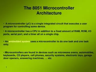
Processor Architecture Harvard versus Princeton – Harvard architecture was largely ignored till the late 70’s when the need for instruction parallelism was felt RISC versus CISC – User-designed operations rather than designer-specified instructions
Intel 8051, Basic Features 12-16 MHz. Clock speed 12-clock cycle per instruction cycle 4 Kbytes of control store 128 bytes of RAM 32 I / O lines Two 8 / 16-bit Timers Multiple internal and external interrupt sources Programmable serial port Interface for upto 128 Kbytes of external memory
Types of Memory The 8051 has three very general types of memory. On-Chip Memory, External Code Memory, and External RAM. On-Chip Memoryrefers to any memory (Code, RAM, or other) that physically exists on the microcontroller itself. External Code Memoryis code (or program) memory that resides off-chip. This is often in the form of an external EPROM. External RAM is RAM memory that resides off-chip. This is often in the form of standard static RAM or flash RAM.
Types of Memory (Contd.) Code Memory Code memory is the memory that holds the actual 8051 program that is to be run. This memory is limited to 64K and comes in many shapes and sizes: Code memory may be found on-chip, either burned into the microcontroller as ROM or EPROM (one of the distinguishing factors from version to version is how much ROM/EPROM space the chip has) . Code may also be stored completely off-chip in an external ROM or, more commonly, an external EPROM. Flash RAM is also another popular method of storing a program.
Types of Memory (Contd.) External RAM The 8051 also supports what is called External RAM. As the name suggests, External RAM is any random access memory which is found off-chip. Since the memory is off-chip it is not as flexible in terms of accessing, and is also slower. For example, to increment an Internal RAM location by 1 requires only 1 instruction and 1 instruction cycle. To increment a 1-byte value stored in External RAM requires 4 instructions and 7 instruction cycles. In this case, external memory is 7 times slower! What External RAM loses in speed and flexibility it gains in quantity. While Internal RAM is limited to 128 bytes (256 bytes with an 8052), the 8051 supports External RAM up to 64K.
Program Memory Map FFFF H External Memory 1000H EA’ = 0 PSEN’ = 0 PSEN’ from 8051 0FFF H Internal Memory 0000H 0FFF H External Memory 0000H Overlap from 0000 to 0FFF h 4K on-chip EPROM* EA’ = 1 EA’ = 0 * On-chip EPROM may be 8K / 16K for other versions
Types of Memory (Contd.) On-chip memory is really one of two types: Internal RAM and Special Function Register (SFR) memory. • Fastest RAM available • Most flexible in terms of reading, writing, and modifying its contents • Internal RAM is volatile • Storage area for the operating stack
Register Banks • The 8051 uses 8 "R" registers (R0, R1, R2, R3, R4, R5, R6, and R7) which are used in many of its instructions. • These registers are generally used to assist in manipulating values and moving data from one memory location to another. • ADD A,R4 is the same as ADD A, 04h as long as the default register bank R0 is chosen
Bit Memory • The 8051, being a communications-oriented microcontroller, gives the user the ability to access 128 bit variables. • To set bit number 24 (hex) to 1 you would execute the instruction:SETB 24h • Writing the value FFh to Internal RAM address 20h, effectively sets bits 00h through 07h • Bit variables 80h and above are actually used to access certain SFRs on a bit-by-bit basis. For example, if output lines P0.0 through P0.7 are all clear (0) and P0.0 output line is to be turned on, then one of these two may be executed: MOV P0,#01h or SETB 80h
Basic Registers • Accumulator • B register – used only in MUL AB and DIV AB • The "R" registers • The Data Pointer (DPTR) - only user-accessible 16-bit register. When the 8051 accesses external memory it will access external memory at the address indicated by DPTR • The Program Counter (PC) - 2-byte address which tells the 8051 where the next instruction to execute is to be found in memory • The Stack Pointer (SP) - When the 8051 is initialized SP will be initialized to 07h. SP is modified by the instructions PUSH, POP, ACALL, LCALL, RET, and RETI and also by interrupts.
Special Function Register (SFR) Memory • Special Function Registers (SFRs) are areas of memory that control specific functionality of the 8051 processor • 4 SFRs permit access to the 8051’s 32 input/output lines • 1 SFR allows reading or writing to the 8051s serial port • Other SFRs allow the user to set the serial baud rate, control and access timers, and configure the 8051s interrupt system • SFRs give the illusion of being Internal Memory MOV 99h, #01h writes “1” into the serial port • SFR addresses may NOT be used as additional RAM memory even if a given address has not been assigned to an SFR • All SFRs whose addresses are divisible by 8 can be accessed with bit operations
SFRs (Contd.) SCON (Serial Control, address 98h, bit-addressable) used to configure the behaviour of the 8051's on-board serial port SBUF (Serial Buffer, address 99h) used to send and receive data via the on-board serial port IE (Interrupt Enable, address A8h,bit-addressable) used to enable and disable specific interrupts IP (Interrupt Priority, address B8h, bit-addressable) used to specify the relative priority of each interrupt PSW (Program Status Word, address D0h, bit-addressable) contains the carry flag, the auxiliary carry flag, the overflow flag, the parity flag and the register bank select flags ACC (Accumulator, address E0h, bit-addressable) B (B Register, address F0h, bit-addressable) A common practice when semiconductor firms wish to develop a new 8051 derivative is to add additional SFRs to support new functions that exist in the new chip.
SFRs (Contd.) The 8051 uses ports P0 and P2 to address the external memory. Thus when using external RAM or code memory only ports P1 and P3 may be made use of SP (address 81h) should be initialized to 2Fh as the first instruction of every program unless the register banks and bit variables are not going to be used PCON (Power Control, address 87h) is used to control the 8051's power control modes TCON (Timer Control, address 88h, bit-addressable) used to configure and modify the way in which the 8051's two timers operate TMOD (Timer Mode, Addresses 89h) used to configure the mode of operation of each of the two timers TL0/TH0 (Timer 0 Low/High, Addresses 8Ah/8Ch) TL1/TH1 (Timer 1 Low/High, Addresses 8Bh/8Dh)
Addressing Modes Immediate AddressingMOV A,#20h Direct Addressing MOV A,30h Indirect Addressing MOV A,@R0 (Indirect addressing always refers to Internal RAM; it never refers to an SFR) External Direct MOVX A,@DPTR MOVX @DPTR,A External IndirectMOVX @R0,A
Program Flow • Conditional BranchingJB 45h LOOP (Jump if bit set) [ Program may only branch to instructions located withim 128 bytes prior to or 127 bytes following the address which follows the conditional branch instruction] • Direct Jumps LJMP NEW_ADDRESS (Long Jump) SJMP NEW_ADDRESS (Short Jump) AJMP NEW_ADDRESS(Jump within same 2K memory block) The LJMP command requires three bytes of code memory whereas both the SJMP and AJMP commands require only two • Subprogram LCALL NEW_ADDRESS and RET
Timers • 2 timers (up counters) • With 11.059 MHz clock and with a single machine cycle consisting of 12 crystal pulses, a running timer will be incremented 11,059,000 / 12 = 921,583 times • Keeping time and/or interval timing • Counting the events themselves • Generating baud rates for the serial port
TIMER MODES 13-bit Time Mode (mode 0) - bits 0-4 of TLx and bits 0-7 of THx 16-bit Time Mode (mode 1) 8-bit Auto Reload Time Mode (mode 2) - THx holds the "reload value" and TLx is the timer itself . Very commonly used for establishing a baud rate Split Timer Mode (mode 3) - When Timer 0 is placed in mode 3, it essentially becomes two separate 8-bit timers (TL0 and TH0 act as Timer 0 and Timer 1). All the bits that are related to Timer 1 will now be tied to TH0. While Timer 0 is in split mode, the real Timer 1 (i.e. TH1 and TL1) can be put into modes 0, 1 or 2 normally
Serial Communication • SCON * : The baud rate indicated in this table is doubled if PCON.7 (SMOD) is set
Serial Communication (Contd.) Writing to the Serial Port CLR TI ; Be sure the bit is initially clearMOV SBUF,#0A ; Send the number 0A to the serial portJNB TI,$ ; Pause until the TI bit is set. The above three instructions will successfully transmit a character and wait for the TI bit to be set before continuing. The last instruction says "Jump if the TI bit is not set, to $"--$, in most assemblers, means "the same address of the current instruction." Thus the 8051 will pause on the JNB instruction until the TI bit is set by the 8051 upon successful transmission of the character .
Serial Communication (Contd.) Reading the Serial Port JNB RI,$ ; Wait for the 8051 to set the RI flagMOV A,SBUF ; Read the character from the serial port The first line of the above code segment waits for the 8051 to set the RI flag; again, the 8051 sets the RI flag automatically when it receives a character via the serial port.
Interrupts • The following events can cause an interrupt: • Timer 0 Overflow • Timer 1 Overflow • Reception/Transmission of Serial Character • External Event 0 • External Event 1
Interrupts(Contd.) IE SFR (address A8h)
Interrupts(Contd.) • Polling Sequence • External 0 Interrupt • Timer 0 Interrupt • External 1 Interrupt • Timer 1 Interrupt • Serial Intrrupt
Interrupts(Contd.) • Two levels of interrupt priority: high and low • Nothing can interrupt a high-priority interrupt--not even another high priority interrupt. • A high-priority interrupt may interrupt a low-priority interrupt. • A low-priority interrupt may only occur if no other interrupt is already executing. • If two interrupts occur at the same time, the interrupt with higher priority will execute first. If both interrupts are of the same priority the interrupt which is serviced first by polling sequence will be executed first. IP SFR (Address B8h)
What Happens When an Interrupt Occurs? • The current Program Counter is saved on the stack, low-byte first. • Interrupts of the same and lower priority are blocked. • In the case of Timer and External interrupts, the corresponding interrupt flag is cleared. • Program execution transfers to the corresponding interrupt handler vector address. • The Interrupt Handler Routine executes.
Serial Interrupts When the serial interrupt is executed, it may have been triggered because the RI flag was set or because the TI flag was set-- or because both flags were set. INT_SERIAL: JNB RI,CHECK_TI; If the RI flag is not set, we jump to check TI MOV A,SBUF; If we got to this line, its because the RI bit *was* set CLR RI; Clear the RI bit after we’ve processed it CHECK_TI: JNB TI,EXIT_INT; If the TI flag is not set, we jump to the exit point CLR TI; Clear the TI bit before we send another character MOV SBUF,#A; Send another character to the serial port EXIT_INT: RETI
Features of 8052, 8051’s big brother 256 bytes of Internal RAM (compared to 128 in the standard 8051) - referred by Indirect Addressing A third 16-bit timer, capable of a number of new operation modes and 16-bit reloads Upto 24 MHz. Clock speed Additional SFRs to support the functionality offered by the third timer. (In addition to the 8051's 21 standard SFRs, the 8052 adds an additional 5 SFRs related to the 8052's third timer – address C8h to CDh)