Chapter 13 Inductance and Inductors
290 likes | 618 Vues
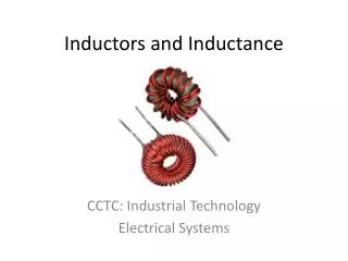
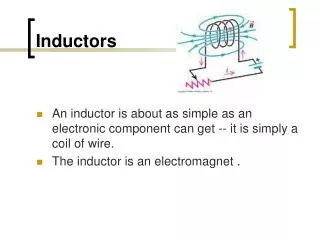
Chapter 13 Inductance and Inductors. 13.0 Preview Inductor [Fig. 13-1, page 493] coil of wire [Fig. 13-1a] effect on circuit operation is to oppose changes in current inductance: property of inductor to oppose current change may referred to as chokes or reactors. Sysmbol [Fig. 13-1b]

Chapter 13 Inductance and Inductors
E N D
Presentation Transcript
Chapter 13 Inductance and Inductors
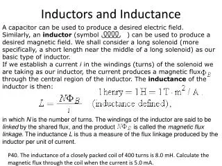
13.0 Preview Inductor [Fig. 13-1, page 493] coil of wire [Fig. 13-1a] effect on circuit operation is to oppose changes in current inductance: property of inductor to oppose current change may referred to as chokes or reactors. Sysmbol [Fig. 13-1b] unit: Henry non-ideal inductor [Fig. 13-1c] applications : tuning circuit in radio receiver ballast circuit that limit current in fluorescent lamp protection circuit used to control short-circuit current
13.1 Electromagnetic Induction [page 494] Motional emf [Fig. 13-2a] the magnet is thrust into the coil the meter deflects upscale the magnet is withdrawn the meter deflects downscale voltage magnitude is proportional to how fast the magnet is moved
Motional emf [Fig 13-2b, page 495] voltage is induced if a conductor is moved through the magnetic field if the conductor is moved to the right, its far end is positive if it is mvoed to the left, the polarity reverses and its far end becomes -ve voltage magnitude is proportional to how fast the wire is moved Mutually induced voltage [Fig. 13-2c, page 495] voltage is induced in coil 2 due to the magnetic field created by the current in coil 1 meter kick upscale at the instance the switch is closed meter kick downscale at the instance the switch is opened
Self-inducted voltage [Fig. 13-2d, page 495] voltage is induced in a coil by its own current the top end of the coil becomes +ve at the isntance the switch is closed the top end of the coil becomes -ve at the instance the switch is opened Faraday’s Law [page 495] voltage is induced in a circuit whenever the flux linking(i.e. passing through) the circuit is changing. the magnitude of the induced voltage is proportional to the rate of change of the flux linkages also stated in terms of the rate of cutting flux lines Lenz’s Law[page 496] the polarity of the induced voltage is such as to oppose the cause producing it
13.2 Induced Voltage and Induction [page 496] Steady DC current [Fig. 13-3a] current is constant, magnetic field is constant induced voltage is zero inductance has no effect on steady, unchanging dc current Increasing current [Fig. 13-3b] increasing current causes expanding field the expanding field induces a voltage that opposes the current build-up the faster the current increases, the larger the opposing voltage Decreasing current [Fig. 13-3c] decreasing current causes collapsing field the collapsing field induces a reversed voltage that opposes the curret decrease the faster the current decreases, the larger the induced voltage
Counter emf [Fig. 13-4, page 497] the induced voltage tries to counter changes in current, it is called a counter emf or back voltage Note: this voltage does not oppose current, it oppose only changes of current it does not prevent the current from changing it only prevents it from changing abruptly Result of back voltage: current in an inductor changes gradually and smoothly from one value to another Refer to Figure 13-4 [page 497] - Current in an inductance (a) Currennt cannot jump from one value to another suddenly. (b) Current must change smoothly with no abrupt jumps.
Iron-core and air-core inductors voltage induced in a coil depends on flux linkages flux linkages depend on core materials Iron-core coils coil with ferromagnetic core flux almost entirely confined to their corespass through all windings flux linkage = N [Fig. 13-5] induced voltage e = N x rate of change of = N (d/dt) Refer to Figure 13-5 [page 497] - When flux passes through all N turns, the flux linking the coil is N .
Example 13-1 [page 497] If the flux through a 200-turn coil changes steadily from 1 Wb to 4 Wb in one second, what is the voltage induced? Solution The flux changes by 3 Wb in one second. Thus, its rate of change is 3 Wb/s. e = N x rate of change of flux = (300 turns) (3 Wb/s) = 600 volts
Air-core coils coil with air or nonferromagnetic core flux not confined to their cores [Fig. 13-6] the flux linking the coil is proportional to current Self-inductance, L (unit: Henry) e = L x rate of change of current = L (di/dt) Refer to Figure 13-6 [page 498], it should be noted that not all flux links all turns. Nonetheless, the flux linking the coil is proportional to current.
13.3 Self-inductance [page 499] the inductance of a coil is one henry if the voltage created by its changing current is one volt when its current changes at the rate of one ampere per second [Fig. 13-8, page 499] voltage across an inductor is denoted by VL rather than by e EXAMPLE 13-2[page 499] If the current through a 5-mH inductance changes at the rate of 1000 A/s, what is the voltage induced? Solution VL = L x rate of change of current = (5 x 10⁻³ H) (1000 A/s) = 5 volts
Inductance formula approximate inductance fo the coil [Fig. 13-9, page 499] L = μN2 A / l (H) where l is in meters, A is in square meters, N is the number of turns, and is the permeability of the core. EXAMPLE 13-3 [page 500] A 0.15 m long air-core coil has a radius of 0.006 m and 120 turns. Compute its inductance. Solution A = r2 = 1.131 x 10⁻⁴m2 = O = 4 x 10⁻⁷ Thus, L = 4 x 10⁻⁷ (120)2 (1.131 x 10⁻⁴)/0.15 = 13.6H
To provide geater inductance in smaller spaces, iron cores are used (before saturation) to solve variable permeability problem after iron core saturated, air gap may be used to control saturation if the gap is wide enough, coil inductance is approximately (Note: equation break down for small 1) L = oN2 Ag / 1g Refer to Fig. 13-10 [page 500] for the iron-core coil with an air gap to control saturation
Example 13-4 [page 500] The inductor of Figure 13-10 has 1000 turns, a 5-mm gap, and a cross-sectional area at the gap of 5 X 10⁻⁴m2. What is its inductance? Solution L = (4 X 10⁻⁷)(1000)2(5 X 10⁻⁴)/(5 X 10-3) = 0.126 H
Practical notes 1.Since inductance is due to a conductor‘s magnetic field, it depends on the same factors that the magnetic field depends on. The stronger the field for a given current, the greater the inductance. Thus, a coil of many turns will have more inductance than a coil of a few turns (L is proportional to N2) and a coil wound on a magnetic core will have greater inductance than a coil wound on a nonmagnetic form. 2. However, if a coil is wound on a magnetic core, the core‘s permeability may change with flux density. Since flux density depends on current and inductance depends on permeability, inductance in this case depends on current, I.e., it is not constant, but is a non-linear function of current. For example, the inductor of Figure 13-11 has a nonlinear inductance due to core saturation. All inductors encountered in this book are assumed to be linear, I.e., of constant value.
13.4 Computing Induced Voltage [page 501] polarity of induced voltage depends on current increasing or decreasing current increases, induced voltage is +ve current decreases, induced voltage is -ve Example 13-5 [page 501] Figure 13-12 is the current through a 10-mH inductance. Determine voltage L and sketch it.
Example 13-5 (Solution) [page 502] Solution Break the problem into intervals over which the slope is constant,determine the slope for each segment, then compute voltage using L = L x slope for that interval: 0 to 1 ms: Slope = 0. Thus, L = 0V. 1 ms to 2 ms: Slope = i / t = 4 A/(1 x 10-3 s) = 4 x 10³ A/s. Thus, L = Li / t = (0.010H)(4 x 10³A/s) = 40V. 2 ms to 2 ms: Slope = i / t = 8 A/(2 x 10-3 s) = 4 x 10³ A/s. Thus,L = Li / t = (0.010H)( 4 x 10³A/s) = 40V. 4 ms to 5 ms: Slope = 0. Thus, L = 0V. 5 ms to 6 ms: Same slope as from 1 ms to 2 ms. Thus, L = 40V. The voltage waveform is shown in Figure 13-13 [page 502].
13.5 Inductances in series and parallel [page 503] same rules as resistance for series case (Fig. 13-15, page 503) LT = L1 + L2 + L3 + …. + LN for parallel case (Fig. 13-16, page 504) 1/LT = 1/L1 + 1/L2 + 1/L3 + …….+ 1/LN For two inductances, LT = L1.L2 / (L1 + L2)
Example 13-6 [page 502] Find LT for the circuit of Figure 13-17 [page 504]. Solution The parallel combination of L2an L3 is This is in series with L1 and L4. Thus, LT= 2.5 + 1.5 + 11 = 15H.
13.6 Practical considerations [page 504] Core types depends on its intended use and frequency range iron core for audio or power supply applications as they need large L air or ferrite cores RF and TV circuits as iron has large power loss ar high frequency Variable inductors changing coil spacing with a screwdriver adjustment threaded ferrite slug is moved in or out of coil’s winding
Refer to Fig. 13-20 [page 505] for Circuit symbols: (a) Iron-core (b) Ferrite-core (c) Variable (d) Air-core Stray capacitance [Fig. 13-21(a), page 506] stray capacitance exists between inductors’s windings effect depends on frequency - neglected on low frequency while take into account on high frequency. In Figure 13-21(a), Cw is stray capacitance.
Stray inductance [page 506] all current-carrying conductors have inductancne leads on circuit components and traces on PCB all have inductance stray inductance is so small that it can be neglected 13.7 Inductance and steady state DC [page 507] ideal iductor looks like short circuit dc equivalent of non-ideal inductor is coil resistance
Example 13.8 [page 507] In Figure 13-24(a), the resistance of the coil is 14.4. What is I? Solution Reduce the circuit as in (b), ETh = (9/15)(120) = 72V RTh = 6 9 = 3.6 Now replace the coil by its dc equivalent circuit as in (b). Thus, I = ETh/RT = 72/(3.6 + 14.4) = 4A
Example 13-9 [page 508] The resistance of coil 1 in Figure 13-25(a) is 30 and that of coil 2 is 15 . Find the voltage across the capacitor assuming steady state dc. Solution Replace each coil inductance with a short circuit and the capacitor with an open circuit. As you can see from (b), the voltage across C is the same as the voltage across RL2. Thus, VC = [Rl2/(Rl1 + Rl2)]E = (15/45)(60) = 20 V
13.8 Eergy stored by an inductance [page 509] energy is stored in its magnetic field when the field collapses, this energy will return to the circuit for ideal inductor with no internal resistance, no power is dissipated power to inductor P = VL i , where VL = L di/dt W = (1/2) L i2 , where i = instantanneous value of current W = (1/2) L I2 , where I = steady state current
Example 13-10 [page 509] The coil of Figure 13-28(a) has a resistance of 15 . When the current reaches its steady state value, the energy stored is 12J. What is the inductance of the coil? Solution [page 510] I = 100 V/25 = 4A W = 1/2LI2 J 12J = 1/2L(4A)2 Thus, L = 2(12)/42 = 1.5 H
13.9 Inductor troubleshooting hints [page 510] Open coil causes: result of poor solder joints or broken connections check: visual inspection disconnect the inductor and check it with ohmmeter (open-circuited coil has infinite resistance) Shorts causes: Shorts occur betweenn windings or between coil and its core check: Result in excessive currennt and overheating Look for burned insulation, discolored component, etc. Use ohmmeter to check for shorts between windings and core Subsitute a known good inductor for the suspected one