Download
1 / 101
1.03k likes | 1.44k Vues
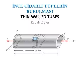
İNCE CİDARLI TÜPLERİN BURULMASI THIN-WALLED TUBES. Kapalı tüpler. Dairesel kesitli-ince cidarlı tüplerin burulması.

E N D
İNCE CİDARLI TÜPLERİN BURULMASITHIN-WALLED TUBES Kapalı tüpler
Dairesel kesitli-ince cidarlı tüplerin burulması İnce cidarlı ve kapalı tüplerin burulma problemleri, Coulomb teorileri ile çözülebilen dairesel tüplerden elde edilen sonuçlardan yararlanarak elemanter olarak çözülebilmektedir. Ortalama yarıçap Cidar kalınlığı
1) Daire kesitli tüpler: İçi boş daire kesitli millerin burulması dikkate alınarak ince cidarlı tüplerin burulma formülleri çıkarılabilir. • İçi boş dairesel kesitlerde maksimum kayma gerilmesi kesitin dış yüzeyine yakın noktalarda meydana gelir: (a) • İnce cidarlı dairesel kesitlerde ortalama kayma gerilmesi cidar boyunca sabit kabul edilir ve aşağıdaki gibi hesaplanır: (b)
İçi boş milin polar atalet momenti: İçi boş dairesel kesitin dış ve iç yarıçapları kullanılarak aşağıdaki gibi bulunur: Dairesel tüplerin polar atalet momenti: Yukarıdaki polar atalet momenti ifadesi aşağıdaki gibi çarpanlara ayrılır: (a) burada şeklindedir. Buna göre polar atalet momenti aşağıdaki gibi olur: (b)
t cidar kalınlığı R ortalama yarıçapı yanında çok küçükse J=2πR3t=2ARt polar atalet momenti kullanılabilir. (b) şeklinde görüldüğü gibi ince cidarlı tüplerde cidar kalınlığı boyunca kayma gerilmelerinin değişmediği kabul edilebilir. Bu durumda Birim dönme açısı ise: burada s ortalama çevre uzunluğudur. Buna göre tüpün toplam dönme açısı aşağıdaki gibi olur:
Örnek:Şekildeki dairesel kesitli mil T=6 kNm’lik bir burulma momentine maruz bırakıldığına göre meydana gelen kayma gerilmesini ve birim dönme açısını hesaplayınız (G=25 GPa). Dış ve iç çaplar sırası ile D=128 mm ve d=122 mm olarak verilmektedir. T=6 kNm d D
Ortalama çap ve cidar kalınlığı: Kesit özellikleri (Alan ve Polar atalet momenti): veya
Cidarda oluşan ortalama kayma gerilmesi: veya Birim dönme (burulma) açısı:
İçi boş mil durumuna göre kayma gerilmesi ve birim dönme açısı:
Non-circularThin-Walled Hollow Shafts The stresses acting on the longitudinal faces a-band cd produce forcesFbandFc(Fig. 3-40d). These forces are obtained by multiplying thestresses by the areas on which they act: in whichtbandtcrepresent the thicknesses of the tube at points band c,respectively (Fig. 3-40d). FIG. 3-40 Thin-walled tube ofarbitrary cross-sectional shape
FIG. 3-40 Thin-walled tube ofarbitrary cross-sectional shape In addition, forcesF1andF1are produced by the stresses acting on faces b-cand a-d. From the equilibrium of the element in the longitudinal direction(the xdirection), we see that Fb=Fc , or
Kayma Akımı (Shear Flow) Because the locations of the longitudinal cuts a-b and c-dwere selected arbitrarily, it follows from the preceding equation that the product of theshear stress τand the thickness t of the tube is the same at every point inthe cross section. This product is known as the shear flow and is denotedby the letter q: or (3-59)
This relationship shows that the largest shear stress occurs where thethickness of the tube is smallest, and vice versa. • Naturally, in regions where thethickness is constant, the shear stress is constant. • Note that shear flow isthe shear force per unit distance along the cross section.
İnce cidarlı tüplerde burulma formülü (Torsion Formula for Thin-Walled Tubes) • The next step in the analysis is to relate the shear flow q(and hence theshear stress τ) to the torque Tacting on the tube. For that purpose, let usexamine the cross-section of the tube, as pictured in Fig. 3-41. r median line FIG. 3-41 Cross section of thin-walled tube
Themedian line (also called the centerlineor the midline) of the wall of thetube is shown as a dashed line in the figure. • We consider an element ofarea of length ds(measured along the median line) and thickness t. • Thedistance sdefining the location of the element is measured along themedian line from some arbitrarily chosen reference point.
The total shear force acting on the element of area is qds, and themoment of this force about any point Owithin the tube is in which ris the perpendicular distance from point Oto the line of actionof the force qds. The total torque Tproduced by the shear stresses is obtained by integrating along the medianline of the cross section: r median line FIG. 3-41 Cross section of thin-walled tube in which Lmdenotes the length of the median line.
The integral abovecan be difficult to integrate by formal mathematicalmeans, but fortunately it can be evaluated easily by giving ita simple geometric interpretation. • The quantity rdsrepresents twicethe area of the shaded triangle shown in Fig. 3-41. • (Note that the trianglehas base length dsand height equal to r.)
Therefore, the integralrepresents twice the area Amenclosed by the median line of the crosssection: • Therefore the shear flow is • Now we can obtain a torsionshearformula for thin-walled tubes:
Dairesel olmayan ince cidarlı tüplerin burulması 2) Herhangi bir biçimdeki tüp kesitli çubuklar: Şekil (a) da görüldüğü gibi herhangi bir kesiti olan çubuk dikkate alalım. Bu çubuktan çok küçük parçayı büyütüp dengesini inceleyelim. Bu eleman dengede olduğundan, örnek olarak karşılıklı kesitlerde bulunan V3ve V4 kesme kuvvetleri de dengededir. ve olur. Kayma gerilmesi cidar kalınlığı çarpımına kayma akımı denir ve q ile gösterilir.
Dik köşelerde, yani birbirine dik kesitlerde kayma gerilmelerinin eşit olması şartından yazılabilir. Buna göre kayma akımları Cidar eksen eğrisi s üzerinde alınan (t ds) alan elemanına etkiyen dV kesme kuvveti veya şeklindedir.
Tüplerde Kayma Gerilmesinin Bulunması Kesit eğrisi boyunca kayma akımlarının eşit olması (q1=q2=q3=…) şartından dVkesme kuvvetinin büyüklüğü de sabit kalır. Bu kesme kuvvetinin kesit düzlemi içerisindeki herhangi bir O noktasına göre momenti, kesite etkiyen T burulma momentine eşit olmalıdır. Bu durumda yazılır. veya
İntegral içindeki (h ds) terimi, şekildeki taralı üçgen (dA) alanının iki katıdır. Buna göre burulma momenti şeklinde olur. Burulma momenti ifadesinden kayma gerilmesi çekilirse aşağıdaki gibi olur:
Buna göre kesitteki en büyük kayma gerilmesi, cidar kalınlığının en küçük olduğu noktada meydana geleceği açıktır. Bu durumda maksimum kayma gerilmesi gibi olur. Burada A kesit cidar orta hattının sınırladığı alandır. A
Tüplerde Burulma Açısının Bulunması Kesitin θ birim dönme açısını hesaplamak için şekil değiştirme enerjisinde yararlanılabilir. T burulma momentinin yaptığı iş, dφ=θdzolduğu bilinerek şeklinde olur. dz boyundaki parçada biriken enerji, τ/2Generji yoğunluğu kullanılarak şeklinde olur. Burada, τ kayma gerilmesi, G kayma modülü ve dVhacim elemanıdır.
Yukarıdaki iş ve enerji ifadesi birbirine eşitlenirse (burada ) elde edilir. Burada dVhacim elemanı olup dV=t dsdzyukarıdaki denklemde yerine konulursa elde edilir. Bu ifade düzenlenirse tüpün birim dönme (burulma) açısı aşağıdaki gibi olur:
Summing forces in the x-direction on AB, • shear stress varies inversely with thickness • Angle of twist (from Chapt 11) Thin-Walled Hollow Shafts • Compute the shaft torque from the integral of the moments due to shear stress
Örnek: Boyutları şekilde verilen tüp, T=50 kNm’lik burulma momentine maruz bırakılıyor. Buna göre: Kesitte meydana gelen en büyük kayma gerilmesini ve yerini bulunuz. Birim dönme açısını hesaplayınız (G=70 GPa)
Example 3.10 Extruded aluminum tubing with a rectangular cross-section has a torque loading of 24 kip-in. Determine the shearing stress in each of the four walls with uniform wall thickness of 0.160 in. and wall thicknesses of 0.120 in. on AB and CD and 0.200 in. on CD and BD.
SOLUTION: • Determine the shear flow through the tubing walls • Find the corresponding shearing stress with each wall thickness
SOLUTION: • Determine the shear flow through the tubing walls
Find the corresponding shearing stress with each wall thickness • with a uniform wall thickness, with a variable wall thickness
İnce Cidarlı Tüplerin Burulması Various thin-walled members
Dikdörtgen kesitli miller Açık tüpler
Torsion of Noncircular Members • Circulartorsion formulas are notvalid for non-circular shafts. • Planar cross-sections of noncircular shafts do not remain planar and stress and strain distribution do not vary linearly • For uniform rectangular cross-sections,
At large values of a/b, the maximum shear stress and angle of twist for other open sections are the same as a rectangular bar.
SAMPLE PROBLEM 3.9 Using τall=40 MPa, determine the largest torque that maybe applied to each of the brass bars. Note that the two solid bars have the same cross-sectionalarea, and that the square bar and square tube havethe same outside dimensions.
3. Square Tube. For a tube of thickness t, the shearing stress is givenby following equation where A is the area bounded by the center line of the cross section. Wehave We substitute τ=τall=40 MPaand t = 6 mm and solve for the allowabletorque:
Örnek: Ortalama yarıçapları R, cidar kalınlıkları t olan kapalı ve açık dairesel tüp kesitli çubuklar T burulma momentine maruz bırakılırsa τmax ve ϴ oranlarını hesaplayınız.