Object-Oriented Analysis and Design
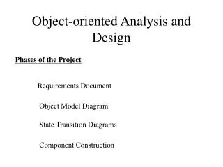
Object-Oriented Analysis and Design. Lecture 6: DESign activities and use case realization. Objectives. Design Discipline Design Activities Develop detailed object-oriented design models Design class diagrams Extend domain model. Moving From Business Modeling Requirements to Design.


Object-Oriented Analysis and Design
E N D
Presentation Transcript
Object-Oriented Analysis and Design Lecture 6: DESign activities and use case realization
Objectives • Design Discipline • Design Activities • Develop detailed object-oriented design models • Design class diagrams • Extend domain model
Moving From Business Modeling Requirements to Design • Business and requirements models • Description: high-level representations • Needs, key processes and functions, environment • Purpose: promote understanding • Design models move project closer to implementation • Models of design discipline are “blueprints” • Design activities carry out business tasks and achieve business objectives
Comparison of Modeling During the Business Modeling, Requirements, and Design Disciplines
Design Use Case Realizations • Use case realizations offer a lower-level view • Two-tiered focus • Class interactions supporting a particular use case • Interactions among software, users, and external systems • Design typically spread over many iterations • UML design class diagrams and interaction diagrams document design
Design the Database • Designing database as a key design activity • Physical model of database based on class diagram • Physical model describes relational or OO database • Some technical issues • Performance, such as response time • Integration with existing databases • Legacy databases
Design the User Interface • User interface issues • User capabilities and needs differ widely • User interacts with the system in different ways • Approaches to interface vary by system • Has nature of interface emerged from earlier models?
What is Object-Oriented Design? • The bridge between a user’s requirements and programming for the new system • “Blueprints”, or design models, are necessary to build systems • An adaptive approach to development • Requirements and design are done incrementally within an iteration • A complete set of designs may not be developed at one time
Overview of Object-Oriented Programs • Object-oriented programs consist of a set of computing objects that cooperate to accomplish a result • Each object has program logic and data encapsulated within it • Objects send each other messages to collaborate • Most object-oriented programs are event-driven • Instantiation of a class creates an object based on the template provided by the class definition
Object-Oriented Design Models • Identify all objects that must work together to carry out a use case • Divide objects into groups for a multilayer design • Interaction diagrams describe the messages that are sent between objects • Includes sequence and communication diagrams • Design class diagrams document and describe the programming classes
Object-Oriented Design Process • Create a first-cut model of the design class diagrams • Develop interaction diagrams for each use case or scenario • Update the design class diagrams • Method names, attributes, and navigation visibility
Design Classes and Design Class Diagrams • Design class diagrams are extensions of domain class model diagrams • Elaborate on attribute details • Define parameters and return values of methods • Define the internal logic of methods • A first-cut design class diagram is based on the domain model and engineering design principles • Interaction diagrams are used to refine a design class diagram as development progresses
Design Class Notation • Class name and stereotype information • Attribute information • Visibility, type-expression, name, initial value, and properties • Method signature • Visibility, name, type-expression, and parameter list • Use the entire signature to identify a method to distinguish between overloaded methods
OStudentclass examples for the domain diagram and the design class diagram
Developing the First-Cut Design Class Diagram • Elaborate the attributes with type and initial value information • Most attributes should be private • Add navigation visibility arrows • Based on which classes need access to which other classes • Can be bidirectional • Will need to be updated as design progresses
Interaction Diagrams–Realizing Use Cases and Defining Methods • Interaction diagrams are at the heart of object-oriented design • Realization of a use case • Determine what objects collaborate by sending messages to each other • Two types • Sequence • Communication
Object Responsibility • Objects are responsible for carrying out system processing • Two major areas of responsibility • Knowing • Knowledge about its own data and about other classes with which it must collaborate to carry out use cases • Doing • All the activities an object does to assist in the execution of a use case
Partial design class diagram for the Look up item availability use case
Designing with Sequence Diagrams • An SSD captures the interactions between the system and the external world represented by actors • The system is treated like a black box • A detailed sequence diagram uses all of the same elements as an SSD • The :System object is replaced by all of the internal objects and messages within the system
First-Cut Sequence Diagram • Determine which other objects may need to be involved to carry out the use case • Replace the :System object with a use case controller object • Determine which other messages will be sent • Define the source and destination object for each message • Use activation lifelines to indicate when an object is executing a method
First-cut sequence diagram for the Look up item availability use case
Guidelines for Preliminary Sequence Diagram Development • Determine all of the internal messages that result from each input message • Define origin and destination objects • Identify the complete set of classes that will be affected by each message • Flesh out the components for each message • Iteration, true/false conditions, return values, and passed parameters
SSD for the telephone order scenario of the Create new order use case
Sequence diagram for the telephone order scenario of the Create new order use case