Survivable Networks – Part II
200 likes | 330 Vues
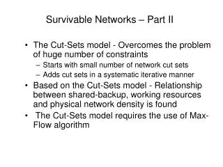
Survivable Networks – Part II. The Cut-Sets model - Overcomes the problem of huge number of constraints Starts with small number of network cut sets Adds cut sets in a systematic iterative manner

Survivable Networks – Part II
E N D
Presentation Transcript
Survivable Networks – Part II • The Cut-Sets model - Overcomes the problem of huge number of constraints • Starts with small number of network cut sets • Adds cut sets in a systematic iterative manner • Based on the Cut-Sets model - Relationship between shared-backup, working resources and physical network density is found • The Cut-Sets model requires the use of Max-Flow algorithm
Points of Concern: Cut-Set Approach • Single-link failure • Complexity of network’s Shared Risk Link Group (SRLG) • Mapping of SRLG • Real (exceptional) SRLG case example • Measuring physical network vulnerability • Control possibilities on recovery routes • Transmission System Modularity
A B E C X D X Duct Multi-link Failure following Fiber Cut Logical SDH/SONET Network (basis for services) - Fiber - SDH Link - XDM - Physical Site - Link Failure D E - Fiber Cut A C B Physical Network (basis for optical network)
Measuring Fiber-infrastructure Vulnerability • Fiber cut per month per X Kilometers in the Metro (MAN) • Fiber cut per month per Y Kilometers in the Long Distance (WAN) • Typical values of X and Y: in the range 100 – 300 Kilometers • In well maintained networks the values X and Y are high
A G F E D B H I J C P-Cycles Principles 1 2 5 3 4 9 7 8 6 10 11 12 13 nr 14 15 For links 4, 7, 10 and 11 that P-Cycle creates two recovery routes For links 2, 3, 5 , 8, 9, 12, 13,15 that P-Cycle creates one recovery route For links 1, 6,14 that P-Cycle does not create any recovery route
P-Cycle 2 K B C G A E H I J D P-Cycle 1 3 17 1 11 4 15 12 2 10 14 5 16 8 13 6 9 7 The P-Cycles Approach Considerations • Choose P-Cycles • Determine their widths Consider Single Fiber-cut Failures: Links 1, 4, 5 - Use twice the capacity of P-Cycle 1; Links 6, 14, 2, 17, 3, 10 - Use once the capacity of P-Cycle 1; Input to P-Cycle models: Working capacities on each fiber
P-Cycles • Main point of concern is how to select the set of R P-Cycles • Current selections of P-Cycles do not include aspects of working capacity on links (based on pure network topology criteria).
Major Survivability Policies Second Failure Line Path } } Cut Set } * * * * Shared Dedicated P-Cycles Hop limit OD-Cycles OD-Cycles } * Split OD-Cycles } } } Proactive Proactive Reactive