Download
1 / 129
1.35k likes | 2.1k Vues
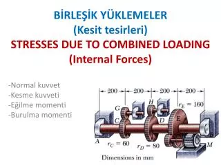
BİRLEŞİK YÜKLEMELER ( Kesit tesirleri ) STRESSES DUE TO COMBINED LOADING ( Internal Forces ). -Normal kuvvet -Kesme kuvveti -Eğilme momenti -Burulma momenti. Eğilmeli Burulma.

E N D
BİRLEŞİK YÜKLEMELER(Kesit tesirleri)STRESSES DUETO COMBINED LOADING(InternalForces) -Normal kuvvet -Kesme kuvveti -Eğilme momenti -Burulma momenti
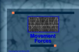
Eğilmeli Burulma Bir mil eğilmeli burulma durumuna maruz kaldığında normal ve kayma gerilmeleri meydana gelir. Şekildeki kasnağa uygulanan P kuvveti A noktasına indirgendiğinde T=PR büyüklüğünde burulma momenti ankastre noktasına indirgendiğinde burulma ile birlikte M=PLbüyüklüğünde eğilme ve V=P büyük-lüğündekesme etkisi meydana gelir.
Özet olarak: Burulmadan dolayı kayma, Eğilmeden dolayı normal, Kesme kuvvetinden dolayı kayma gerilmesi meydana gelir.
3. Maddede belirtilen kesme kuvvetinin yol açtığı kayma gerilmesi milin merkezinde maksimum değerine ulaşmış olup, eğilme ve burulma gerilmelerine göre çok küçük olduğundan genellikle hesaba katılmaz. Eğilme gerilmeleri kesitin en üstünde ve en altında en büyük değerlerde meydana gelir.
Dolu miller için atalet momentleri ve gerilmeler: - Polar atalet momenti ve kayma gerilmesi: - Kesit atalet momenti ve normal gerilme:
Maksimum normal gerilmeye göre mil çapının bulunması: Gevrek malzemeler normal gerilmelere hassas olduklarından maksimum normal gerilme emniyet gerilmesine eşitlenerek mil çapı bulunur: Dolu miller: ve
İçi boşaltılmış miller: Atalet momentleri:
Kayma gerilmesi ve normal gerilme: ve Asal gerilmeler:
Maksimum kayma gerilmesine göre mil çapının bulunması Sünek malzemeler kayma gerilmelerine hassas olduklarından maksimum kayma gerilmesi kayma emniyet gerilmesine eşitlenerek mil çapı bulunur: Dolu miller:
İçi boş miller: Kayma ve normal gerilmeleri: ve Asal gerilmeler:
Örnek: Şekildeki mile bağlı kasnak teğetsel P kuvvetine maruz bırakıldığına göre mil çapını belirleyiniz. P=10 kN R=250 mm L=0.6 m 2R D P L P
Çözüm: Eğilme ve burulma momentleri Max. normal gerilmeye göre mil çapının bulunması
Max. kayma gerilmesine göre mil çapının bulunması olduğundan büyük olan değer kullanılır ve emniyetli çap olarak alınır.
Örnek: Çapı D=40 mm olan milin H ve K noktalarındaki normal ve kayma gerilmelerini hesaplayınız. a=50 mm
Kesit tesirleri (İç kuvvetler): y Kesit özellikleri: x z H K
H Noktasında oluşan gerilmeler: Normal gerilme: y x z H Kayma gerilmesi: K
K Noktasında oluşan gerilmeler: Normal gerilme: y x Kayma gerilmesi: z H K
Örnek: Şekildeki tüp p iç basıncına, T burulma momentine ve Neksenel kuvvetine maruz kaldığına göre tüpte meydana gelen asal gerilmeleri ve maksimum kayma gerilmesini hesaplayınız. T=6 kNm p=2 Mpa N=20 kN d=122 mm D=128 mm p D d T T N N Tüpün kesit görünüşü Tüpün maruz kaldığı yükler
Çözüm: Tüpte oluşan gerilme bileşenleri y x
Tüpün polar atalet momenti ve oluşan kayma gerilmesi Tüpte oluşan normal gerilme
Tüpün ortalama çapı ve cidar kalınlığı Tüpte oluşan eksenel gerilme Tüpte oluşan teğetsel gerilme Eksenel bileşke gerilme
Örnek: Şekildeki ABD kolu A ucundan ankastre olup D ucuna P=900 N büyüklüğünde bir kuvvet uygulandığına göre: H noktasındaki normal ve kayma gerilmelerini hesaplayınız. H noktasındaki asal gerilmeleri hesaplayıp doğrultularını bir eleman üzerinde gösteriniz.
Sample Problem 8.3 Solid shaft rotates at 480 rpm and transmits 30 kW from the motor to gears G and H; 20 kW is taken off at gear G and 10 kW at gear H. Knowing thatτall= 50 MPa, determine the smallest permissible diameter for the shaft.
SOLUTION: • Determine the gear torques and corresponding tangential forces. • Find reactions at A and B. • Identify critical shaft section from torque and bending moment diagrams. • Calculate minimum allowable shaft diameter.
RelationshipamongPower, SpeedandTorque in shafts To determine the torque exerted on the shaft, we recall from elementary dynamics that the power Passociated with the rotationof a rigid body subjected to a torque Tis
Determine the gear torques and corresponding tangential forces. Observing that f =480 rpm =8 Hz, wedetermine the torqueandtangential forcesexerted on gear E:
wedetermine the torques andtangential forcesexerted on gearsC andD:
Critical Transverse Section: Wecompute resultantbendingmoments at all potentiallycritical sections MCor MD
Critical Transverse Section: we findequivalentmomentsforCandD : Cross-section at D Therefore, maximum value ofequivalentmomentoccurs just to the rightof D
Calculate minimum allowable shaft diameteraccordigtomaximumshearingstress:
Sample Problem 8.5 Three forces are applied to a short steel postas shown. Determine the principle stresses, principal planes and maximum shearing stress at point H.
SOLUTION STEPS: • Determine internal forces in Section EFG. • Evaluate normal stress at H. • Evaluate shearing stress at H. • Calculate principal stresses and maximum shearing stress. • Determine principal planes.
Solution: • Determine internal forces in Section EFG. • Section properties,
Sample Problem 8.5 • Calculate principal stresses and maximum shearing stress. Determine principal planes.
Eccentric Axial Loading in a Plane of Symmetry • Stress due to eccentric loading found by superposing the uniform stress due to a centric load and linear stress distribution due a pure bending moment • Eccentric loading • Validity requires stresses below proportional limit, deformations have negligible effect on geometry, and stresses not evaluated near points of load application.
Example 4.07 An open-link chain is obtained by bending low-carbon steel rods of 12-mm diameterinto the shape shown. For a load of700 N, determine a) maximum tensile and compressive stresses in thestraightportion of the link, b) Thedistance between sectionthe centroidaland neutral axis of a cross-section.
SOLUTION STEPS: • Find the equivalent centric load and bending moment • Superpose the uniform stress due to the centric load and the linear stress due to the bending moment. • Evaluate the maximum tensile and compressive stresses at the inner and outer edges, respectively, of the superposed stress distribution. • Find the neutral axis by determining the location where the normal stress is zero.