Download
1 / 87
1.12k likes | 1.72k Vues
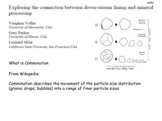
Energy Use in Comminution. Lecture 7 MINE 292. COMMINUTION MECHANICAL CHEMICAL External Special Chemical forces forces forces - smashing - thermal shock - digestion

E N D
Energy Use in Comminution Lecture 7 MINE 292
COMMINUTION MECHANICAL CHEMICAL External Special Chemical forces forces forces - smashing - thermal shock - digestion - blasting (chemical) - microwaves - dissolution - breaking - pressure changes - combustion - attrition - photon bombardment - bioleaching - abrasion - splitting or cutting - crushing - grinding
Comminution • Although considered a size-reduction process, since minerals in an ore break preferentially, some upgrading is achieved by size separation with screens and/or classifiers
Comminution and Sizes Effective Range of 80% passing sizes by Process ProcessF80 P80 1) Explosive shattering: infinite 1 m 2) Primary crushing: 1 m 100 mm 3) Secondary crushing: 100 mm 10 mm 4) Coarse grinding: 10 mm 1 mm 5) Fine grinding: 1 mm 100 µm 6) Very fine grinding: 100 µm 10 µm 7) Superfine grinding: 10 µm 1 µm The 80% passing size is used because it can be measured.
Comminution - Blasting • Blasting practices aim to minimize explosives use • Pattern widened/explosive type limited to needs • Requirements – maximum size to be loaded • However, "Mine-to-Mill" studies show that • Increased breakage by blasting reduces grinding costs • Blasting energy efficiency ranges from 10-20% • Crushing and grinding energy efficiencies are 1-2% • Limitations in blasting relate to • Flyrock control • Vibration control • Improvements comes from reduced top-size & Wi
Primary Crushing • Jaw crusher < 1,000 tph • Underground applications • Gyratory crusher > 1,000 tph • Open-pit and In-pit
Primary Crushing • Product size = 10 – 4 inches (250 – 100 mm) • Open Side Setting (OSS) is used to operate • Mantle and bowl are lined with steel plates • Spider holds spindle around which the mantle is wrapped
Secondary Crushing • Symons Cone Crushers • Standard and Shorthead Secondaries Tertiaries CSS (mm) 25-60 5-20 • Can process up to 1,000 tph • Mech. Availability = 70-75%
Secondary Crushing Plants • Fully-configured Plant
Secondary Crushing Plants • No Internal Surge Bins
Secondary Crushing Plants • No Screen Bin
Secondary Crushing Plants • Open Circuit – gravity-flow
Impact Crushers • Used in small-scale operations • Coarse liberation sizes • Hammer velocities (50mps) • Screen hole size controls product size • High wear rates of hammers and screen
Impact Crushers • Barmac Crusher • Invented in New Zealand • Impact velocity = 60 -90 mps • High production of fines by attrition • Used in quarries & cement industry
Impact Crushers • Barmac Crusher • Invented in New Zealand • Impact velocity = 60-90 mps • High production of fines by attrition • Used in quarries & cement industry
Secondary Crushing - Rolls Crusher • Angle of Nip • Standard rolls • HPGR forces • Packed-bed • 2a = bed thickness • Now applied to fine crushing • Competitive with SAG (or complementary)
Energy in Comminution • Crushing and Grinding • Very inefficient at creating new surface area (~1-2%) • Surface area is equivalent to surface energy • Comminution energy is 60-85 % of all energy used • A number of energy "laws" have been developed • Assumption - energy is a power function of D • dE = differential energy required, • dD = change in a particle dimension, • D = magnitude of a length dimension, • K = energy use/weight of material, and • n = exponent
Energy in Comminution • Von Rittinger's Law (1867) • Energy is proportional to new surface area produced • Specific Surface Area (cm2/g) inverse particle size • So change in comminution energy is given by: • which on integration becomes: • where Kr = Rittinger's Constant and • fc = crushing strength of the material
Energy in Comminution • Kick's Law (1883) • Energy is proportional to percent reduction in size • So change in comminution energy is given by: • which on integration becomes: • where Kk = Kick's Constant and • fc = crushing strength of the material
Energy in Comminution • Bond's Law • Energy required is based on geometry of a crack expansion as it opens up • His analysis resulting in a value for n of 1.5: • which on integration becomes: • where Kb = Bond's Constant and • fc = crushing strength of the material
Energy in Comminution • Where do these Laws apply? • Hukki put together the diagram below (modified on right) • Kick applies to coarse sizes (> 10 mm) • Bond applies down to 100 µm • Rittinger applies to sizes < 100 µm
Size Reduction • Different fracture modes • Leads to different size distributions • Bimodal distribution not often seen in a crushed or ground product
Breakage in Tension • All rocks (or brittle material) break in tension • Compression strength is 10x tensile strength • Key issue is how a compression or torsion force is translated into a tensile force • As well, the density and orientation of internal flaws is a key issue (i.e., microcracks, grain boundaries, dislocations)
Griffith’s Crack Theory • Three ways to cause a crack to propagate: Mode I – Opening (tensile stress normal to the crack plane) Mode II – Sliding (shearing in the crack plane normal to tip) Mode III – Tearing (shearing in the crack plane parallel to tip)
Griffith’s Crack Theory • Based on force (or stress) needed to propagate an elliptical plate-shaped or penny-shaped crack where A = area of the elliptical plate E' = effective Young’s Modulus = strain s = specific surface energy a = half-length of the ellipse
Young's Modulus • Also called Tensile Modulus or Elastic Modulus • A measure of the stiffness of an elastic material • Ratio of uniaxial stress to uniaxial strain • Over the range where Hooke's law holds • E' is the slope of a stress-strain curve of a tensile test conducted on a sample of the material
Young's Modulus Low-carbon steel Hooke's law is valid from the origin to the yield point (2). 1. Ultimate strength 2. Yield strength 3. Rupture 4. Strain hardening region 5. Necking region A: Engineering stress (F/A0) B: True stress (F/A)
Griffith’s Theory Differentiating with respect to 'a' gives: Rearranging derives the fracture stress to initiate a crack as well as the strain energy release rate, G: where G = energy/unit area to extend the crack
Compression Loading • Fracture under point-contact loading D. Tromans and J.A. Meech, 2004. "Fracture Toughness and Surface Energies of Covalent Materials: Theoretical Estimates and Application to Comminution", Minerals Engineering 17(1), 1–15.
Induced stresses-compressive load P P P KI =Ysi(ai)1/2 At fracture: KIC =Ysic(ai)1/2 where KIC =(EGIC)1/2 GIC = Fracture Toughness a1 s1 a5 s4 a2 s2 s5 s3 2a4 2a3 P KI = Stress intensity (at fracture KI = KIC, si = sic) si = Tensile stress, ai = crack length Y = Geometric factor (2 π-½) E = Young's modulus, GIC = critical energy release rate/m2
Schematic of particle containing a crack (flaw) of radius 'a' subjected to compressive force 'P' (a) (b) P P s s s k k s s P s P P k k P P P 2 a D D q 2 a s s s k s k s k s k P P P P P P P P si = sP( kcosq - sinq ) KI=YsP(kcosq - sinq ) a1/2 At fracture KI=KIC. In theory there is a limiting average fine particle size: Dlimit ~ π(KIC/ksP)2(where q = 0)
Impact Efficiency • KIC, P, and flaw orientation (θ) determine impact efficiency • Impact without fracture elastically deforms the particle with theelastic strain energy released as thermal energy (heat) • Impact inefficiency leads directly to high-energy consumption • In ball and rod mills with the random nature of particle/steel interactions, a wide distribution of "P" occurs leading to very inefficient particle fracture. A way to narrow this distribution is to use HPGR • Such mills consume less energy and exhibit improved inter-particle separation in mineral aggregates (i.e., liberation via inter-phase cracking), particularly with diamond ores • Diamond liberation without fracture damage is attributable to the high KIC of diamond relative to that of the host rock
Comminution Testing • Single Particle Breakage Tests • Drop weight testing • Split Hopkinson Bar tests • Pendulum testing • Multiple Particle Breakage Tests • Bond Ball Mill test • Bond Rod Mill test • Comparison test • High-velocity Impact Testing
Drop Weight Test 2 to 3 inch pieces of rock are subjected to different drop weight energy levels to establish Wi(C)
Split Hopkinson Bar Test Apparatus • Method to obtain material properties in a dynamic regime • Sample is positioned between two bars: • - incident bar • - transmission bar • A projectile accelerated by compressed air strikes the incident bar causing an elastic wave pulse. • Pulse runs through first bar - part reflected at the bar end, the other part runs through sample into transmission bar. • Strain gauges installed on surfaces of incident and transmission bars measure pulse strain to determine amplitudes of applied, reflected, and transmitted pulses.
Pendulum Test – twin pendulum Impact Pendulum Rebound Pendulum Rock Particle
Bond Impact Crushing Test – Wi(C) Low-energy impact test pre-dates Bond “Third Theory” paper. Published by Bond in 1946 Test involves 2 hammers striking a 2"-3" specimen simultaneously on 2 sides. Progressively more energy (height) added to hammers until the specimen breaks Doll et al (2006) have shown that drill core samples can be used to establish range of energy requirements
Bond Impact Crushing Test – Wi(C) • Values measured are: • E= Energy applied at breakage (J) • w= Width of specimen (mm) • ρ = Specific gravity • Wi(C) = _59.0·E_ • w·ρ • where Wi(C) = Bond Impact Crushing Work Index (kWh/t) F.C. Bond, 1947. "Crushing Tests by Pressure and Impact", Transactions of AIME, 169, 58-66. A. Doll, R. Phillips, and D. Barratt, 2010. "Effect of Core Diameter on Bond Impact Crushing Work Index", 5th International Conference on Autogenous and Semiautogenous Grinding Technology, Paper No. 75, pp.19.
Bond Impact Crushing Test – Wi(C) Some example results: A. Doll, R. Phillips, and D. Barratt, 2010. "Effect of Core Diameter on Bond Impact Crushing Work Index", 5th International Conference on Autogenous and Semiautogenous Grinding Technology, Paper No. 75, pp.19.
Bond Mill – to determine Wi(RM) For a Wi(RM) test, the standard Closing screen size should be closing sieve size is 1180μm. close to desired P80 Multiply desired P80 by √2 Stage crush 1250 ml of feed to pass 12.7 mm (0.5 in) Perform series of batch grinds in standard Bond rod mill - 1' D x 2' L (0.305 m x 0.610 m) Wave liners Mill speed = 40 rpm Charge = 8 rods (33.38 kg)
Bond Mill – to determine Wi(RM) • Initial sample = 1250 ml stage-crushed to pass 12.7 cm (0.5 in) • Grind initial sample for 100 revolutions, applying "tilting" cycle • Run level for 8 revs, then tilt up 5° for one rev, then down • at 5° for one rev, then return to level and repeat the cycle • Screen on selected ‘closing’ screen to remove undersize. Add back an equal weight of fresh feed to return to original weight. • Return to the mill and grind for a predetermined number of revolutions calculated to produce a 100% circulating load. • Repeat at least 6 times until undersize produced per mill rev reaches equilibrium. Average net mass per rev of last 3 cycles to obtain rod mill grindability (Gbp) in g/rev. • Determine P80 of final product.
Bond Mill – to determine Wi(BM) For a Wi(BM) test, the standard Closing screen size should be closing sieve size is 150μm. close to desired P80 Multiply desired P80 by √2 Stage crush 700 ml of feed to pass 3.35 mm (0.132 in) Perform series of batch grinds in standard Bond ball mill - 1' D x 1' L (0.305 m x 0.305 m) Smooth liners / rounded corners Mill speed = 70 rpm Charge = 285 balls (20.125 kg)
Bond Mill – to determine Wi(BM) • Initial sample = 700 ml stage-crushed to pass 3.35 cm • Grind initial sample for 100 revolutions, no "tilting" cycle used • Screen on selected ‘closing’ screen to remove undersize. Add back an equal weight of fresh feed to return to original weight. • Return to the mill and grind for a predetermined number of revolutions calculated to produce a 250% circulating load. • Repeat at least 7 times until undersize produced per mill rev reaches equilibrium. Average net mass per rev of last 3 cycles to obtain ball mill grindability (Gbp) in g/rev. • Determine P80 of final product.
Effect of Circulating Load on Wi(BM) From S. Morrell, 2008. "A method for predicting the specific energy requirement of comminution circuits and assessing their energy utilization efficiency", Minerals Engineering, 21(3), 224-233.
Bond Mill – Wi(BM) or Wi(RM) Procedure: use lab mill of set diameter with a set ball or rod charge and run several cycles (5-7) of grinding and screening to recycle coarse material into next stage until steady state (i.e., recycle weight becomes constant). Formula: where Wi = work index (kWh/t); P = 80% passing size of the product; F = 80% passing size of the feed; Gbp = net grams of screen undersize per mill revolution; P1 = closing screen size (mm)
Size Ranges for Different Comminution Tests Property Soft Medium Hard Very Hard Bond Wi (kWh/t) 7 - 9 9 -14 14 -20 > 20