Direct-Current Nanogenerator Driven by Ultrasonic Waves
130 likes | 469 Vues
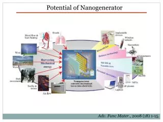
Direct-Current Nanogenerator Driven by Ultrasonic Waves. Bryan Schubert EE C235 April 9, 2008. X. Wang, J. Song and Z. L. Wang, Science 316 , 102 (2007). Application. Energy scavenging Remote powering of implanted devices Force/pressure sensors.

Direct-Current Nanogenerator Driven by Ultrasonic Waves
E N D
Presentation Transcript
Direct-Current Nanogenerator Driven by Ultrasonic Waves Bryan Schubert EE C235 April 9, 2008 X. Wang, J. Song and Z. L. Wang, Science316, 102 (2007).
Application • Energy scavenging • Remote powering of implanted devices • Force/pressure sensors X. Wang, J. Song and Z. L. Wang, Science316, 102 (2007).
Principle of operation • Piezoelectric effect: • d is piezoelectric coefficient Z. L. Wang and J. Song, Science312, 242 (2006).
Pt-ZnO Schottky barrier Principle of operation AFM scan of nanowire array Z. L. Wang and J. Song, Science312, 242 (2006).
Nanowire contact scenarios: I. & II. Nanowire is bent until compressed side contacts electrode. III. Resonating nanowire. IV. Compressed nanowire. Principle of operation X. Wang, J. Song and Z. L. Wang, Science316, 102 (2007).
Fabrication • ZnO Nanowires • Grown on Al2O3, using Au particles as catalyst for Vapor-Liquid-Solid process. • 10/μm2 density • 1 μm long • 40 nm diameter • Pt-coated Si zigzag electrode • Wet-etching* • 1 μm peak-to-peak • 200 nm Pt layer • Total device • 2 x 106μm2 area X. Wang, J. Song and Z. L. Wang, Science316, 102 (2007). *J. Frühauf and S. Krönert, Microsyst. Technol.11, 1287 (2005).
Performance • Equivalent circuit • Vs, nanowire source • Ri, active NW contact resistance w/ electrode • Rw, inactive NW resistance – 30 kΩ • Rc, measurement device contact resistance w/ electrode – 30 Ω • IA ≈ Vs/(Rc+Ri) • V ≈ -VsRw/(Ri+Rw) • Output for 41 kHz wave • 0.15 nA increase in IA • V = -0.7 mV output • R = 3.56 kΩ • Estimated 250 to 1000 NW engaged X. Wang, J. Song and Z. L. Wang, Science316, 102 (2007).
Performance • Alternative designs • CNTs are not piezoelectric • Flat electrode does not allow contact of compressed edge. X. Wang, J. Song and Z. L. Wang, Science316, 102 (2007).
Performance • Durability • Can produce dc output for over 1 hour • Power • 1 to 4 fW per fiber • 1 pW total output • 0.00125 to 0.005% of fibers contribute • Efficiency* • Mechanical-to-electrical, 17 to 30% X. Wang, J. Song and Z. L. Wang, Science316, 102 (2007). * Z. L. Wang and J. Song, Science312, 242 (2006)
Improvements • Control nanowire dimensions to optimize power per nanowire (1 fW to 10 fW per fiber). • Control spacing and patterning to optimize nanowire co-operation (10 μW/cm2 => 0.2 μW for this device).