Network layer
Explore the essential functions of the network layer in computer networking. This includes segment encapsulation into datagrams, routing decision-making, and forwarding packets through routers. Learn about the concepts of virtual circuits and datagram networks, and the significance of routing algorithms like RIP and OSPF. Gain insights into how routers handle datagram formats, manage routing tables, and ensure efficient data delivery, along with the distinctions between network and transport layer services. Ideal for networking professionals and students.

Network layer
E N D
Presentation Transcript
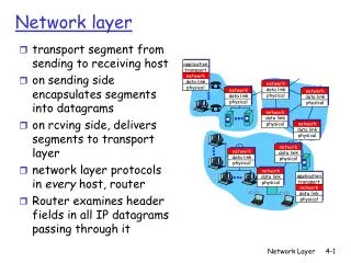
transport segment from sending to receiving host on sending side encapsulates segments into datagrams on rcving side, delivers segments to transport layer network layer protocols in every host, router Router examines header fields in all IP datagrams passing through it network data link physical network data link physical network data link physical network data link physical network data link physical network data link physical network data link physical network data link physical application transport network data link physical application transport network data link physical Network layer Network Layer
Two Key Network-Layer Functions • forwarding: move packets from router’s input to appropriate router output • routing: determine route taken by packets from source to dest. • routing algorithms analogy: • routing: process of planning trip from source to dest • forwarding: process of getting through single interchange Network Layer
routing algorithm local forwarding table header value output link 0100 0101 0111 1001 3 2 2 1 value in arriving packet’s header 1 0111 2 3 Interplay between routing and forwarding Network Layer
Connection setup • 3rd important function in some network architectures: • ATM, frame relay, X.25 • before datagrams flow, two end hosts and intervening routers establish virtual connection • routers get involved • network vs transport layer connection service: • network: between two hosts (may also involve inervening routers in case of VCs) • transport: between two processes Network Layer
For individual datagrams: guaranteed delivery guaranteed delivery with less than 40 msec delay For a flow of datagrams: in-order datagram delivery guaranteed minimum bandwidth to flow restrictions on changes in inter-packet spacing Network service model Q: What guarantees for “channel” transporting datagrams from sender to receiver? Network Layer
Network layer service models: Guarantees ? Network Architecture Internet ATM ATM ATM ATM Service Model best effort CBR VBR ABR UBR Congestion feedback no (inferred via loss) no congestion no congestion yes no Bandwidth none constant rate guaranteed rate guaranteed minimum none Loss no yes yes no no Order no yes yes yes yes Timing no yes yes no no Network Layer
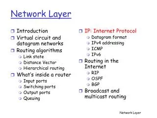
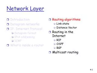
4. 1 Introduction 4.2 Virtual circuit and datagram networks 4.3 What’s inside a router 4.4 IP: Internet Protocol Datagram format IPv4 addressing ICMP IPv6 4.5 Routing algorithms Link state Distance Vector Hierarchical routing 4.6 Routing in the Internet RIP OSPF BGP 4.7 Broadcast and multicast routing Chapter 4: Network Layer Network Layer
VC implementation VCs consists of: • Signaling protocol -> find path from source to destination • VC numbers, one number for each link along path • entries in forwarding tables in routers along path • packet belonging to VC carries VC number (rather than dest address) • VC number can be changed on each link. • New VC number comes from forwarding table Network Layer
used to setup, maintain teardown VC used in ATM, frame-relay, X.25 not used in today’s Internet application transport network data link physical application transport network data link physical Virtual circuits: signaling protocols 6. Receive data 5. Data flow begins 4. Call connected 3. Accept call 1. Initiate call 2. incoming call Network Layer
VC number 22 32 12 3 1 2 interface number Incoming interface Incoming VC # Outgoing interface Outgoing VC # 1 12 3 22 2 63 1 18 3 7 2 17 1 97 3 87 … … … … Forwarding table Forwarding table in northwest router: Routers maintain connection state information! Network Layer
no call setup or network-level concept of “connection” packets forwarded using destination host address packets between same source-dest pair may take different paths application transport network data link physical application transport network data link physical Datagram networks 1. Send data 2. Receive data Network Layer
Forwarding table 4 billion possible entries Destination Address RangeLink Interface 11001000 00010111 00010000 00000000 through 0 11001000 00010111 00010111 11111111 11001000 00010111 00011000 00000000 through 1 11001000 00010111 00011000 11111111 11001000 00010111 00011001 00000000 through 2 11001000 00010111 00011111 11111111 otherwise 3 Network Layer
Longest prefix matching Prefix MatchLink Interface 11001000 00010111 00010 0 11001000 00010111 00011000 1 11001000 00010111 00011 2 otherwise 3 Examples Which interface? DA: 11001000 00010111 00010110 10100001 Which interface? DA: 11001000 00010111 00011000 10101010 Network Layer
4. 1 Introduction 4.2 Virtual circuit and datagram networks 4.3 What’s inside a router 4.4 IP: Internet Protocol Datagram format IPv4 addressing ICMP IPv6 4.5 Routing algorithms Link state Distance Vector Hierarchical routing 4.6 Routing in the Internet RIP OSPF BGP 4.7 Broadcast and multicast routing Chapter 4: Network Layer Network Layer
Router Architecture Overview Both main routing-layer functions: • run routing algorithms/protocol (RIP, OSPF, BGP) • forwarding datagrams from incoming to outgoing link Network Layer
Input Port Functions Routing layer: • goal: complete input port processing at ‘line speed’ • queuing: if datagrams arrive faster than forwarding rate into switch fabric • Forwarding: either to: • routing processor • output link (decentralized switching) Physical layer: bit-level reception Data link layer: e.g., Ethernet see chapter 5 Network Layer
Input Port Queuing • Fabric slower than input ports combined -> queueing may occur at input queues • Head-of-the-Line (HOL) blocking: queued datagram at front of queue prevents others in queue from moving forward • queueing delay and loss due to input buffer overflow! Network Layer
Three types of switching fabrics Network Layer
Memory Input Port Output Port System Bus Switching Via Memory First generation routers: • traditional computers with switching under direct control of CPU • packet copied to system’s memory • speed limited by memory bandwidth (2 bus crossings per datagram) Network Layer
Switching Via a Bus • datagram from input port memory to output port memory via a shared bus • bus contention: switching speed limited by bus bandwidth Network Layer
Switching Via An Interconnection Network • overcome bus bandwidth limitations • Banyan networks, other interconnection nets initially developed to connect processors in multiprocessor • Advanced design: fragmenting datagram into fixed length cells, switch cells through the fabric. Network Layer
Output Ports • Buffering required when datagrams arrive from fabric faster than the transmission rate • Scheduling discipline chooses among queued datagrams for transmission Network Layer
Output port queueing • buffering when arrival rate via switch exceeds output line speed • queueing (delay) and loss due to output port buffer overflow! Network Layer
4. 1 Introduction 4.2 Virtual circuit and datagram networks 4.3 What’s inside a router 4.4 IP: Internet Protocol Datagram format IPv4 addressing ICMP IPv6 4.5 Routing algorithms Link state Distance Vector Hierarchical routing 4.6 Routing in the Internet RIP OSPF BGP 4.7 Broadcast and multicast routing Chapter 4: Network Layer Network Layer
IP address: 32-bit identifier for host, router interface interface: connection between host/router and physical link router’s typically have multiple interfaces host typically has one interface IP addresses associated with each interface 223.1.1.2 223.1.2.2 223.1.2.1 223.1.3.2 223.1.3.1 223.1.3.27 IP Addressing: introduction 223.1.1.1 223.1.2.9 223.1.1.4 223.1.1.3 223.1.1.1 = 11011111 00000001 00000001 00000001 223 1 1 1 Network Layer
IP address: subnet part (high order bits) host part (low order bits) What’s a subnet ? Devices that can physically reach each other without intervening router Must have same subnet part of IP address Subnets 223.1.1.1 223.1.2.1 223.1.1.2 223.1.2.9 223.1.1.4 223.1.2.2 223.1.1.3 223.1.3.27 subnet 223.1.3.2 223.1.3.1 network consisting of 3 subnets Network Layer
Recipe To determine the subnets, detach each interface from its host or router, creating islands of isolated networks. Each isolated network is called a subnet. 223.1.1.0/24 223.1.2.0/24 223.1.3.0/24 Subnets Subnet mask: /24 Network Layer
How many? Subnets 223.1.1.2 223.1.1.1 223.1.1.4 223.1.1.3 223.1.7.0 223.1.9.2 223.1.9.1 223.1.7.1 223.1.8.1 223.1.8.0 223.1.2.6 223.1.3.27 223.1.2.1 223.1.2.2 223.1.3.1 223.1.3.2 Network Layer
host part subnet part 11001000 0001011100010000 00000000 200.23.16.0/23 IP addressing: CIDR CIDR:Classless InterDomain Routing • subnet portion of address of arbitrary length • address format: a.b.c.d/x, where x is # bits in subnet portion of address Network Layer
IP addresses: how to get one? Q: How does host get IP address? • hard-coded by system admin in a file • Wintel: control-panel->network->configuration->tcp/ip->properties • UNIX: /etc/rc.config • DHCP:Dynamic Host Configuration Protocol: dynamically get address from as server • “plug-and-play” (more in next chapter) Network Layer
IP addresses: how to get one? Q: How does network get subnet part of IP addr? A: gets allocated portion of its provider ISP’s address space ISP's block 11001000 00010111 00010000 00000000 200.23.16.0/20 Organization 0 11001000 00010111 00010000 00000000 200.23.16.0/23 Organization 1 11001000 00010111 00010010 00000000 200.23.18.0/23 Organization 2 11001000 00010111 00010100 00000000 200.23.20.0/23 ... ….. …. …. Organization 7 11001000 00010111 00011110 00000000 200.23.30.0/23 Network Layer
200.23.16.0/23 200.23.18.0/23 200.23.30.0/23 200.23.20.0/23 . . . . . . Hierarchical addressing: route aggregation Hierarchical addressing allows efficient advertisement of routing information: Organization 0 Organization 1 “Send me anything with addresses beginning 200.23.16.0/20” Organization 2 Fly-By-Night-ISP Internet Organization 7 “Send me anything with addresses beginning 199.31.0.0/16” ISPs-R-Us Network Layer
200.23.16.0/23 200.23.18.0/23 200.23.30.0/23 200.23.20.0/23 . . . . . . Hierarchical addressing: more specific routes ISPs-R-Us has a more specific route to Organization 1 Organization 0 “Send me anything with addresses beginning 200.23.16.0/20” Organization 2 Fly-By-Night-ISP Internet Organization 7 “Send me anything with addresses beginning 199.31.0.0/16 or 200.23.18.0/23” ISPs-R-Us Organization 1 Network Layer
IP addressing: the last word... Q: How does an ISP get block of addresses? A: ICANN: Internet Corporation for Assigned Names and Numbers • allocates addresses • manages DNS • assigns domain names, resolves disputes Network Layer
NAT: Network Address Translation rest of Internet local network (e.g., home network) 10.0.0/24 10.0.0.1 10.0.0.4 10.0.0.2 138.76.29.7 10.0.0.3 Datagrams with source or destination in this network have 10.0.0/24 address for source, destination (as usual) All datagrams leaving local network have same single source NAT IP address: 138.76.29.7, different source port numbers Network Layer
NAT: Network Address Translation • Motivation: local network uses just one IP address as far as outside world is concerned: • range of addresses not needed from ISP: just one IP address for all devices • can change addresses of devices in local network without notifying outside world • can change ISP without changing addresses of devices in local network • devices inside local net not explicitly addressable, visible by outside world (a security plus). Network Layer
NAT: Network Address Translation Implementation: NAT router must: • outgoing datagrams:replace (source IP address, port #) of every outgoing datagram to (NAT IP address, new port #) . . . remote clients/servers will respond using (NAT IP address, new port #) as destination addr. • remember (in NAT translation table) every (source IP address, port #) to (NAT IP address, new port #) translation pair • incoming datagrams:replace (NAT IP address, new port #) in dest fields of every incoming datagram with corresponding (source IP address, port #) stored in NAT table Network Layer
2 4 1 3 S: 138.76.29.7, 5001 D: 128.119.40.186, 80 S: 10.0.0.1, 3345 D: 128.119.40.186, 80 1: host 10.0.0.1 sends datagram to 128.119.40.186, 80 2: NAT router changes datagram source addr from 10.0.0.1, 3345 to 138.76.29.7, 5001, updates table S: 128.119.40.186, 80 D: 10.0.0.1, 3345 S: 128.119.40.186, 80 D: 138.76.29.7, 5001 NAT: Network Address Translation NAT translation table WAN side addr LAN side addr 138.76.29.7, 5001 10.0.0.1, 3345 …… …… 10.0.0.1 10.0.0.4 10.0.0.2 138.76.29.7 10.0.0.3 4: NAT router changes datagram dest addr from 138.76.29.7, 5001 to 10.0.0.1, 3345 3: Reply arrives dest. address: 138.76.29.7, 5001 Network Layer
NAT: Network Address Translation • 16-bit port-number field: • 65,536 simultaneous connections with a single LAN-side address! • NAT is controversial: • routers should only process up to layer 3 • violates end-to-end argument • NAT possibility must be taken into account by app designers, eg, P2P applications • address shortage should instead be solved by IPv6 Network Layer
4. 1 Introduction 4.2 Virtual circuit and datagram networks 4.3 What’s inside a router 4.4 IP: Internet Protocol Datagram format IPv4 addressing ICMP IPv6 4.5 Routing algorithms Link state Distance Vector Hierarchical routing 4.6 Routing in the Internet RIP OSPF BGP 4.7 Broadcast and multicast routing Chapter 4: Network Layer Network Layer
IPv6 • Initial motivation:32-bit address space soon to be completely allocated. • Additional motivation: • header format helps speed processing/forwarding • header changes to facilitate QoS • Changes • fixed-length 40 byte header • no fragmentation allowed • Checksum:removed entirely to reduce processing time at each hop • Options: allowed, but outside of header, indicated by “Next Header” field • ICMPv6: new version of ICMP • additional message types, e.g. “Packet Too Big” • multicast group management functions Network Layer
Transition From IPv4 To IPv6 • Not all routers can be upgraded simultaneous • no “flag days” • How will the network operate with mixed IPv4 and IPv6 routers? • Tunneling: IPv6 carried as payload in IPv4 datagram among IPv4 routers Network Layer
F A B E F E B A tunnel Logical view: IPv6 IPv6 IPv6 IPv6 Physical view: IPv6 IPv6 IPv6 IPv6 IPv4 IPv4 Tunneling Network Layer
Flow: X Src: A Dest: F data Flow: X Src: A Dest: F data Flow: X Src: A Dest: F data Flow: X Src: A Dest: F data A B E F F A B E C D Src:B Dest: E Src:B Dest: E Tunneling tunnel Logical view: IPv6 IPv6 IPv6 IPv6 Physical view: IPv6 IPv6 IPv6 IPv6 IPv4 IPv4 A-to-B: IPv6 E-to-F: IPv6 B-to-C: IPv6 inside IPv4 B-to-C: IPv6 inside IPv4 Network Layer
Spring Break Review • Network Layer • Routing • Forwarding • (Network Setup/Teardown) • Virtual Circuits • Datagram Networks • Routers • Input ports, output ports, switching fabric • Queues: HOL blocking & Many-to-1 • IP Addresses, Subnets, CIDR Network Layer
4. 1 Introduction 4.2 Virtual circuit and datagram networks 4.3 What’s inside a router 4.4 IP: Internet Protocol Datagram format IPv4 addressing ICMP IPv6 4.5 Routing algorithms Link state Distance Vector Hierarchical routing 4.6 Routing in the Internet RIP OSPF BGP 4.7 Broadcast and multicast routing Chapter 4: Network Layer Network Layer
5 3 5 2 2 1 3 1 2 1 x z w u y v Graph abstraction Graph: G = (N,E) N = set of routers = { u, v, w, x, y, z } E = set of links ={ (u,v), (u,x), (v,x), (v,w), (x,w), (x,y), (w,y), (w,z), (y,z) } Network Layer
5 3 5 2 2 1 3 1 2 1 x z w y u v Graph abstraction: costs • c(x,x’) = cost of link (x,x’) • - e.g., c(w,z) = 5 • cost could always be 1, or • inversely related to bandwidth, • or inversely related to • congestion Cost of path (x1, x2, x3,…, xp) = c(x1,x2) + c(x2,x3) + … + c(xp-1,xp) Question: What’s the least-cost path between u and z ? Routing algorithm: algorithm that finds least-cost path Network Layer
routing algorithm local forwarding table header value output link 0100 0101 0111 1001 3 2 2 1 value in arriving packet’s header 1 0111 2 3 Interplay between routing and forwarding Network Layer
Global: all routers have complete topology, link cost info “link state” algorithms Decentralized: router knows physically-connected neighbors, link costs to neighbors iterative process of computation, exchange of info with neighbors “distance vector” algorithms Two Classes of Routing Network Layer