Advances in OCDMA: Enhancing Security and Uncoordinated Access in Optical Networks
This report outlines progress in optical code division multiple access (OCDMA) research at UCLA. Key goals include improving security over assigned wavelengths through cryptographically secure wavelength hopping, and exploring uncoordinated access wherein users communicate efficiently without synchronization. Highlights include successive decoding techniques for optimal channel performance, the design of low-density parity-check (LDPC) codes for Z-channels, and algorithms to maximize throughput and maintain acceptable performance in communication systems.

Advances in OCDMA: Enhancing Security and Uncoordinated Access in Optical Networks
E N D
Presentation Transcript
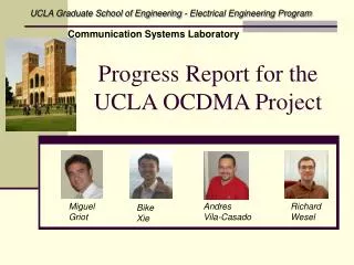
UCLA Electrical Engineering Department-Communication Systems Laboratory UCLA Progress Report OCDMA Channel Coding Jun Shi Andres I. Vila Casado Miguel Griot Richard D. Wesel
OCDMA Goals: Security • Improve security over assigned-wavelength WDM? • UCLA answer: Cryptographically secure wavelength hopping. • A special case of “wheat and chaff” where the other users are the chaff. (Ron Rivest 1998) • Criticism: Requires Synchronization of all users. • Hey, that’s a good point! • We’ll spend the rest of our program on that.
OCDMA Goals: Uncoordinated Access • Can two users in a large optical network communicate efficiently without coordinating with the other users in the network? • There are two types of coordination: • Synchronization at the bit or frame level. • Assignment (as in wavelength assignment) • Note that WDM does not require synchronization, but it does require assignment. • If a system requires central assignment of “codes” then it requires coordination.
The OR Channel User 1 Output User 2 + User n • No multi-level detection (receiver detects only presence of light) • This means that the channel can be seen as an OR channel (1+ X = 1; 0 + X = X) • With proper thresholding, bit synchronization is the worst case.
Main results this quarter • LDPC design for the Z Channel • Density Evolution • Design technique : Linear programming based on density evolution • Status • Simple codes for immediate hardware implementation
Successive Decoding • We can decode the first user by treating others as noise, then the first user’s ones become erasures for the other users. Proceed in this way until finish decoding all the users. • This is called successive decoding. For binary OR channel, this process does not lose capacity as compared to joint decoding.
Successive Decoding: The Z-Channel • Successive decoding for n users: • User with lowest rate is decoded first • Other users are treated as noise • The decoded data of the first user is used in the decoding of the remaining users • First user sees a “Z-channel” • Where ai=1-(1-p)n-i is the probability that at least one of the n-i remaining users transmits a 1
Successive Decoding: Z with erasures • Intermediate users see the following channel assuming perfect previous decoding • Where bi=1-(1-p)i-1 is the probability that at least one of the I-1previously decoded users transmitted a 1 Xi 1 - a1 Yi 0 0 bi e ai (1-bi) bi 1 1 1-bi
Successive Decoding • The last user sees a BEC channel Xn Yn 1 - a1 0 0 a1 e a1 1 1 1 - a1
Successive Decoding • For two users • User 1 sees a Z-channel • User 2 sees the following channel • When BER1 is small, the channel can be approximated to a BEC X2 Y2 1 - p 0 0 p(1-BER1) p(BER1) e p(1-BER1)+(1-p)BER1 1 1 (1-p)(1-BER1) + p(BER1)
A 3-user example R1 1 User 1 User 2 User 3 1 1 R3 R2 User 1 1 1 User 2 User 3 0 0 Receiver
A 3-user example R1 1 User 1 User 2 User 3 1 1 R3 R2 User 1 1 1 User 2 e User 3 0 0 Receiver
A 3-user example R1 1 User 1 User 2 User 3 1 1 R3 R2 User 1 1 1 User 2 e User 3 0 0 Receiver
A 3-user example R1 1 User 1 User 2 User 3 1 1 R3 R2 User 1 User 2 User 3 Receiver
LDPC codes • There are essentially two elements that must be designed when building and LDPC code : • Degree distributions • Edge positioning • This group has worked a lot on the edge positioning problem, thus we have all the necessary designing tools • Also, the degree distribution design problem for symmetric channels (AWGN, BSC, BEC) has been thoroughly studied by many authors.
LDPC codes for asymmetric channels • Density evolution is a concept developed by Richardson et al. that helps predict the LDPC code behavior in symmetric channels • This concept can be used in the design of good degree distribution in many different ways • Wang et al. recently generalized Richardson’s result for asymmetric channels. • We took all these concepts and tried several different linear programming based algorithms, and built a program that efficiently designs degree distributions for any binary memoryless channel. • Given a channel, the program tries to maximize the rate while maintaining an acceptable performance.
0.371989 0.380872 0.389073 0.396646 0.403669 0.410180 0.416236 0.421862 0.427106 0.431998 0.436565 0.440834 0.444828 0.448566 0.452070 0.455357 0.458442 0.461342 0.464062 0.466625 0.469032 0.471299 0.473436 0.475448 0.477345 0.479132 0.480820 0.482412 0.483915 0.485333 0.486675 0.487941 0.489139 0.490271 0.491342 0.492354 0.493311 0.494217 0.495076 0.495891 0.496662 0.497393 0.498086 0.498743 0.499366 0.499957 0.500516 0.501047 0.501550 0.502027 Capacity 0.532439 Rates Degree Distribution Design for Z-channels Target alpha = 0.2731 l(x) = 0.27571047 x + 0.15042832 x2 + 0.18575028 x3 + 0.38811080 x11
-0.051744 -0.026240 -0.003107 0.017941 0.037158 0.054751 0.070872 0.085686 0.099326 0.111926 0.123588 0.134406 0.144449 0.153785 0.162473 0.170558 0.178103 0.185163 0.191761 0.197937 0.203717 0.209134 0.214218 0.218996 0.223478 0.227695 0.231663 0.235397 0.238912 0.242225 0.245348 0.248085 0.250882 0.253517 0.256000 0.258348 0.260559 0.262657 0.264637 0.266504 0.268278 0.269951 0.271536 0.273036 0.274453 0.275797 0.277072 0.278278 0.279422 0.280506 0.281533 0.282507 0.283431 0.284306 0.285137 0.285925 0.286673 0.287384 0.288059 0.288703 0.289321 0.289910 0.290461 0.290986 0.291486 0.291964 Capacity 0.321928 Rates Degree Distribution Design for Z-channels Target alpha = 0.5
Simple codes • In order to have a hardware demo working for the May meeting, some very simple codes were produced. • This demo consists of two transmitter and two receivers • Both receivers decode the information independently
Simple Codes for Demo • Short codes have been designed for a simple demo for 2 users • These were chosen to be as simple to encode and decode as possible • Each bit is encoded separately • Bit synchronism is assumed, blocked asynchronism is allowed • Coordination is required • These codes are error free
Simple codes for Demo (2) 1 Rate 1/4 0 0 Source 2 Source 1 1 1 2 3 4 1 2 3 4 5 6 Rate 1/6 0 1 Receiver 1 looks for position of 0 (which always exists) If 1 or 2, decide 1 If 3 or 4, decide 0 Sum Rate 5/12
Simple codes for Demo (2) 1 Rate 1/4 0 0 Source 2 Source 1 1 1 2 3 4 1 2 3 4 5 6 Rate 1/6 0 1 Receiver 1 looks for position of 0 (which always exists) If 1 or 2, decide 1 If 3 or 4, decide 0 Sum Rate 5/12
Simple codes for Demo (2) 1 Rate 1/4 0 0 Source 2 Source 1 1 1 2 3 4 1 2 3 4 5 6 Rate 1/6 0 1 Receiver 1 looks for position of 0 (which always exists) If 1 or 2, decide 1 If 3 or 4, decide 0 Sum Rate 5/12 Receiver 2 looks for FIRST position of 0. If 1, 3 or 5, decide 1 If 2, 4 or 6, decide 0 Worst Case : block i block i+1
Simple codes for Demo (2) 1 Rate 1/4 0 0 Source 2 Source 1 1 1 2 3 4 1 2 3 4 5 6 Rate 1/6 0 1 Receiver 1 looks for position of 0 (which always exists) If 1 or 2, decide 1 If 3 or 4, decide 0 Sum Rate 5/12 Receiver 2 looks for FIRST position of 0. If 1, 3 or 5, decide 1 If 2, 4 or 6, decide 0 Worst Case : block i block i+1
OR Channel • Channel capacity for a two user OR channel
Density Transformer First approach • After the density transformer each user transmits a one with probability p
Density Transformer • The output bits of a binary linear code (such as LDPC codes) are equally likely 1 or 0 if the information bits are also equally likely • Thus we need to change this distribution in order to avoid such a large interference between users Transmitter: Non-uniform mapper 1) Mapper 2) Huffman Decoder Receiver: Use soft Huffman encoder
Future work in Successive Decoding • Design degree distributions that work well for the specific channels that the different users see • Develop the distribution transformer • Test this successive decoding idea with a simulation.
Joint decoding • Joint decoding will be done on graphs that look like this one • The formulas necessary in this joint decoding have already been found and simplified
Future work on Joint decoding • Develop a density evolution based design tool to construct good LDPC codes for joint decoding • Test and compare the performance of joint decoding and successive decoding • Also evaluate and compare the complexity of both techniques