Exchange Bias: Interface vs. Bulk Magnetism
540 likes | 847 Vues
Miyeon Cheon Hongtao Shi Zhongyuan Liu Jorge Espinosa David Lederman. Exchange Bias: Interface vs. Bulk Magnetism. Hendrik Ohldag Joachim St ö hr. Elke Arenholz. Department of Physics. Optical and Vibrational Spectroscopies Symposium: A Tribute to Manuel Cardona August 20, 2010.

Exchange Bias: Interface vs. Bulk Magnetism
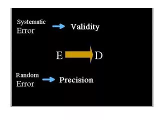
E N D
Presentation Transcript
Miyeon Cheon Hongtao Shi Zhongyuan Liu Jorge Espinosa David Lederman Exchange Bias: Interface vs. Bulk Magnetism HendrikOhldag Joachim Stöhr ElkeArenholz Department of Physics Optical and Vibrational Spectroscopies Symposium: A Tribute to Manuel Cardona August 20, 2010
MR HC HE FM AF Exchange Bias MR: “Remanent” magnetization - Maximum value of M - Depends on FM HC: Coercivity - Depends on FM magnetic anisotropy - Represents energy required to reverse magnetic domain HE: Exchange Bias -Absent in pure FM, results from AF-FM interaction
Ferromagnetic layers ~1.0-5.0 nm thick Insulator/NM Metal ~1.0-2.5 nm Free magnetic layer (analyzes electron spin) Antiferromagnet ~10 - 50 nm Pinned magnetic layer (polarizes tunneling electrons) 1 - 100 mm Pinning Antiferromagnet q Application: Magnetic Tunnel Junction /GMR Sensors Albert Fert & Peter Grünberg 2007 Nobel Prize in Physics “for the discovery of Giant Magnetoresistance”
How does the pinning of bottom FM layer work? (www.research.ibm.com)
Key Questions • Given that: • All EB models require presence of uncompensated magnetization in the antiferromagnet (interface) • Details of EB behavior (e.g. temperature dependence, magnitude) depend strongly on AF anisotropy (bulk) • Some key questions are: • Can uncompensated moments in the AF be detected? • Can the effects of uncompensated moments in the AF be studied systematically? • Can the magnetic anisotropy be studied systematically?
weak anisotropy antiferromagnet [001] dilute antiferromagnet [001] [001] MF2 Antiferromagnets • NiF2 • Rutile structure (a = 0.4651 nm, c = 0.3084 nm) • Antiferromagnetic, TN= 73 K • Weak ferromagnetic • Magnetization lies in the a-b plane • FeF2 • Rutile structure (a = 0.4704 nm, c = 0.3306 nm) • Antiferromagnetic, TN=78 K • Magnetization along the c-axis • ZnF2 • Rutile structure (a = 0.4711 nm, c = 0.3132 nm) • non-magnetic
So… where does Manuel Cardona fit in? Naïve graduate student asks: can antiferromagnetic superlattice magnons be observed? Two-magnon Raman line for 1.3 mm FeF2 thin film
Growth and Characterization • MBE co-deposition of FeF2 (e-beam) and ZnF2, NiF2 (K-cell), Pbase = 7 x 10⁻¹⁰ Torr, Pgrowth < 4 x 10⁻⁸ Torr • TS(AF) = 297 0C, poly-Co @125 0C, poly-MgF2 @RT • Growth along (110) • Twin sample holder – simultaneous growth of underlayer, different overlayers • In-situ RHEED, AFM • X-ray diffraction and reflectivity • Cooling field (HCF = 2 kOe) in the film • plane along the c-axis of FexZn1-xF2 • M vs Hvia SQUID magnetometer, • horizontal sample rotator
Key Questions • Can uncompensated moments in the AF be detected? • Can the effects of uncompensated moments in the AF be studied systematically? • Can the magnetic anisotropy be studied systematically?
e- e- e- e- • Antiferromagnetic Domains Magnetic Dichroism in X-ray Absorption X-ray magnetic circular dichroism sensitive to FM order. Fe L3, L2 NiO L2a, L2b X-ray magnetic linear dichroism sensitive to AF order. Element specific technique sensitive to antiferromagnetic as well as ferromagnetic order.
Einc || [001] Einc || [110] Antiferromagnetic Order of FeF2(110) FeF2 L2 absorption edge Stronger XMLD signal for Co/FeF2(110) compared to bare FeF2(110) indicates an increase in antiferromagnetic order caused by exchange to the FM Co layer.
Measy 2 nm Pd cap 2.5 nm Co 68 nm FeF2 MgF2(110) sub. Mpinned Interface Coupling and Exchange Bias RT Ferromagnet 15K Interface Room T: “Free” uncompensated moments follow FM Low T: Additional “pinned” uncompensated moments antiparallel to easy direction.
Results • Fe in FeF2/Co interface, despite being non-metallic, has • Unpinned magnetization to RT • Pinned magnetization to TB • AF order verified to TNvia XMLD • Co at interface • TB~TN • HC peak near TB Ohldag et al., PRL 96, 027203 (2006)
Parallel Interface Coupling and Exchange Bias 2.) XMCD is indication of interfacial magnetic order at RT. 1.) XMLD and long range AF order vanish at TN. Related to enhancement of coercivity for T >> TN (Grimsditch et al, PRL 2003) Also, see Roy et al, PRL 2006
Key Questions • Can uncompensated moments in the AF be detected? • Uncompensated moments exist in AF, not due to “metallization” • Pinned uncompensated moments in AF vanish near TN • Unpinned uncompensated moments exist up to RT, well above TN • Can the effects of uncompensated moments in the AF be studied systematically? • Can the magnetic anisotropy be studied systematically?
[001] [001] Systems FexNi1-xF2 FexZn1-xF2 Random anisotropy antiferromagnet Dilute antiferromagnet Systematic study of uncompensated M
Effects of Dilution • Domain state model: dilute AF should make small domain creation easier due to nonmagnetic impurities (Malozemoff model) • Net magnetization of AF domains should increase effective interface interaction
Previous Results Co1-xMgxO/ CoO (0.4 nm) /Co P. Miltényi, et al., Phys. Rev. Lett., 84, 4224 (2000)
Sample Profile 5 nm MgF2 Cap (110)-MgF2 Sub 5 nm MgF2 Cap (110)-MgF2 Sub 18 nm Cobalt (F) 18 nm Cobalt (F) Pure interface layer (PIL) 1.0 nm FeF2 65 nm (110) FexZn1-xF2(AF) 65 nm (110) FexZn1-xF2 (AF) Magnetic interface changes with x in FexZn1-xF2
HE, HC Dependence on T PIL affects HE, HC; no effect on TB
HE, HC vs. Temperature for x = 0.75 • HE changes sign as T increases to TB. • HC has two peaks corresponding to HE = 0. • Therefore AF ground state is not unique
TBvs. x in FexZn1-xF2 TB agrees reasonably well with bulk TN data
Interface EnergyDependence on x T = 5K ΔE = -tCo*HE*MS • No large HE enhancement observed • Small AF domains not formed at large x ?
Key Questions • Can uncompensated moments in the AF be detected? • Uncompensated moments exist in AF, not due to “metallization” • Pinned uncompensated moments in AF vanish near TN • Unpinned uncompensated moments exist up to RT, well above TN • Can the effects of uncompensated moments in the AF be studied systematically? • Uncompensated M does not necessarily lead to HE enhancement; critical concentration of impurities must be achieved • However, uncompensated M dependent on defect concentration • Can the magnetic anisotropy be studied systematically?
[001] [001] Systems FexNi1-xF2 FexZn1-xF2 Random anisotropy antiferromagnet Dilute antiferromagnet Systematic study of AF anisotropy
[001] [001] Magnetic Order FeF2 • Rutile structure (a = 0.4704 nm, c = 0.3306 nm) • Antiferromagnet, TN=78 K • Magnetization along the c-axis • NiF2 • Rutile structure (a = 0.4651 nm, c = 0.3084 nm) • Antiferromagnetic, TN= 73 K (80 K in films) • Weak ferromagnet • Magnetization lies in the a-b plane
5 nm Al,Pd cap 18 nm Co 50 nm FexNi(1-x)F2 MgF2(110) sub. [001] [001] Growth and measurements MBE Growth • MgF2 (110) substrate • Growth temperature 210 ˚C • Fe concentration: 0.0, 0.05, 0.21, 0.49, 0.55 1.0 magnetic anisotropy changes with x. x=0.0 x=1.0
[001] FexNi1-xF2 Expectations For nearest neighbor interactions For small f, there is a critical Fe concentration xcbeyond which spins will lie along the c-axis: q q+f For FeF2 and NiF2xc= 0.14
5 K FeF2/Co NiF2/Co 49 nm NiF2 / 16 nm Co H┴ c H || c • Exchange bias along c-axis • TB~ 81 K • No exchange bias along c-axis H. Shi et al., Phys. Rev. B69, 214416 (2004).
Fe0.05Ni0.95F2/Co • For 50 K ≤ T ≤ 70 K • No exchange bias • Wide hysteresis loop • For T ≤ 45 K • Negative exchange bias along the c-axis • Asymmetric saturation magnetization • For 75 K ≤ T • No exchange bias
Large coercivity loops of Fe0.05Ni0.95F2/Co • For 50 K ≤ T ≤ 70 K, large coercivity loops appear for the scanning field range -10 kOe to 10 kOe. • Negative exchange bias (HE ~ -500 Oe) for T = 50 K and 55 K
Fe0.21Ni0.79F2/Co • For 45 K ≤ T ≤ 70 K • No exchange bias effect • Wide hysteresis loop • Similar behavior to Fe0.05Ni0.95F2/Co • Negative HE along the c-axis at T≤ 40 K • Asymmetric saturation magnetization • For 75 K ≤ T • HE = 0
Large HC loops of Fe0.21Ni0.49F2/Co • For 40 K ≤ T ≤ 70 K, large HC loops appear for the scanning field range ±10 kOe • Negative exchange bias effect (HE ~ - 1000 Oe) for 40 K ≤ T ≤55 K
Fe0.49Ni0.51F2/Co • For T≤ 15 K • Negative exchange bias • Asymmetric saturation magnetization • For 50 K ≤ T ≤ 65 K • No exchange bias • Wide hysteresis loop • For 25 K ≤ T ≤ 50 K • Positive exchange bias • Asymmetric saturation magnetization • For 70 K ≤ T • No exchange bias
Large HC loops of Fe0.49Ni0.51F2/Co • For 5 K ≤ T ≤ 55 K, large HC loops appear for H=± 70 kOe • Positive exchange bias effect with HE ≥10 kOe • For 55 K ≤ T ≤ 70 K, large HC loops appear for H = ±10 kOe
Magnetization measurement • Exchange bias studies after field cooling with 2000 Oe from 95 K with SQUID • Measurement direction: c-axis • Measurement sequence: 70 kOe → -70 kOe → 70 kOe, ( ) 70 kOe → -20 kOe → 70 kOe, ( ) -70 kOe, 20 kOe → -70 kOe → 20 kOe ( ) M H 70 kOe -20 kOe 20 kOe -70 kOe Is it Possible to Control the Sign of HE?
Fe0.49Ni0.51F2/Co • Tunable exchange bias (reversal of wide hysteresis loop)
MCo Muncompensated Reversible Exchange Bias • MCo favors parallelexchange coupling with Muncompensated Consistent with micromagnetic modeling M. Cheon, Z. Liu, and D. Lederman, Appl. Phys. Lett. 90, 012511 (2007)
Summary for FexNi(1-x)F2/Co bilayers TN Note low TB Note sign change of HE correlated with DM (same as in FeZnF2 samples) Uncompensated magnetization Exchange bias and coercive field (note low TB)
Fe0.05Ni0.95F2/Co Fe0.21Ni0.79F2/Co 30 K 30 K 1 nm FeF2 20 K 20 K What about FeZnF2? Can HE be Reversed at Low T? Fe0.36Zn0.64F2/Co no effect at 5K
Key Questions • Can uncompensated moments in the AF be detected? • Uncompensated moments exist in AF, not due to “metallization” • Pinned uncompensated moments in AF vanish near TN • Unpinned uncompensated moments exist up to RT, well above TN • Can the effects of uncompensated moments in the AF be studied systematically? • Uncompensated M does not necessarily lead to HE enhancement; critical concentration of impurities must be achieved • However, uncompensated M dependent on defect concentration • Can the magnetic anisotropy be studied systematically? • Low magnetic anisotropy leads to reversible HE, in addition to low TB, as a result of reversal of “pinned” uncompensated M in the AF • Low TB ≠ low TN • Reversible HE requires uncompensated M in the AF • Dilute AF system can also be reversed, but only at higher temperatures due to coupling of H to uncompensated magnetization
Remaining Questions • How universal is the effect of uncompensated moments in the AF? • Can it explain, e.g., low TB ,in other AFs? • Is it possible to engineer desirable interface exchange properties by manipulating AF anisotropy? • What is the size of the AF domains? And does their size really matter? • If they don’t matter, what is the coupling mechanism and where does the uncompensated magnetization come from? • Strain (piezomagnetism)? • Defects? • Update: surprisingly, domain size does not seem to matter much – see Fitzsimmons et al., PRB 77, 22406 (2008).
T = 565 °C 5 nm Al,Pd cap 18 nm Co 50 nm FexNi(1-x)F2 MgF2(110) sub. Areas of Interest Exchange bias GMR in anisotropic structures Self-assembly and surface dynamics Magnetic Nanostructures and Interfaces YMnO3/GaN Hybrid Multifunctional Heterostructures Myoglobin Single Electron Transistor Biomolecular Electronics
T = 565 °C 5 nm Al,Pd cap 18 nm Co 50 nm FexNi(1-x)F2 MgF2(110) sub. Areas of Interest Exchange bias GMR in anisotropic structures Self-assembly and surface dynamics Magnetic Nanostructures and Interfaces YMnO3/GaN Hybrid Multifunctional Heterostructures Myoglobin Single Electron Transistor Biomolecular Electronics
Uncompensated M, x=0.75 Sign change of HE due to reversal of AF structure H. Shi and D. Lederman, Phys. Rev. B66, 094426 (2002)
Measurement Procedure H HCF Jint F Jint AF 1. Cool in HCFfrom above T = TN 2. Measure M vs. H at T < TN Conventional view: Interface exchange interaction sets low T antiferromagnet configuration
Direct Exchange Mechanism • Direct exchange mechanism (Meiklejohn and Bean, 1956) predicts • a) wrong magnitude (~100 times too large) • b) no exchange bias in compensated or disordered surfaces HE = 0 F Jint AF Ideal Uncompensated Compensated Roughness
Random Exchange at Interface • Due to interface roughness, defects, etc. • Antiferromagnetic domains created with local exchange satisfied during cooling L = domain size in AF Malozemoff, 1987