FEA of Wind Turbine Tower
180 likes | 339 Vues
FEA of Wind Turbine Tower. Martin Knecht. The Problem. FEA modeling of a wind turbine tower. Analysis: Stress Deflection Want to prevent Yielding Excessive deflection. Tower Construction. Steel pipe Diameter: 1.850 in. Thickness: 0.225 in. Length: 15 ft. Base

FEA of Wind Turbine Tower
E N D
Presentation Transcript
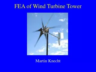
FEA of Wind Turbine Tower Martin Knecht
The Problem • FEA modeling of a wind turbine tower. • Analysis: • Stress • Deflection • Want to prevent • Yielding • Excessive deflection
Tower Construction • Steel pipe • Diameter: 1.850 in. • Thickness: 0.225 in. • Length: 15 ft. • Base • Pipe screewed into 5” flange. • Flange welded to 30” square, ¼ in. thick steel plate.
Tower Construction • Bracket • Houses the permanent magnet alternator (PMA) • Six carbon fiber blades attached to PMA • Total weight of PMA, blades and bracket: 22.25 lb
Tower Construction • Anchoring • Four ¼ inch steel cables • Breaking strength: 7000 lb • Attached 10 feet above the base of the tower (can not be attached higher due to blades) • Anchored 10 feet away from the base on the roof.
Tower Construction • Purpose for FEA is safety: • Constructed around expensive equipment • Solar panels • Weather monitoring station • Constructed near edge of roof.
Loading and Conditions of Operation • FEA modeled for high winds (60 and 100 mph) • Constraints • Rigid constraint at base • Cables (“ropes”) • Loads • Weight of PMA, blades and bracket: 22.25 lb • PMA torque • Wind drag
Loads • PMA torque: • Torque due to PMA is negligible. • With 33 mph winds it produces ~7.8e-4 lb-ft • PMA stops generating power at high wind speeds as a safety factor • Not included in FEA • Wind drag • Determined using the relationship: Drag = ½ Cdrv2A • air density = r = 1.2 kg/m3 • Wind speed = v = 60 and 100 mph • Cross sectional area = A = 0.258 m2 • Coefficient of drag = Cd ~ 1 • Drag at 60 mph = 25 lb • Drag at 100 mph = 70 lb
The FEA Model 1 ft • Pipe mesh • Split into three sections in order to mesh. • Each meshed separately • Needed to be aware of concentrated stresses at pipe boundaries. • Fixed constraint on bottom of flange • “Rope” constraints to model cables
The FEA Model • Loads applied to bracket at the top of pole. • Total body forces of 25 or 70 lb in x-direction to model the wind drag • Downward total body force of 22.3 lb to model the weigh of the turbine • The weight should be offset from the bracket to more realistically model the distribution of mass of the turbine
The FEA Model • Meshing • Would not mesh using h-adaptively if entire model was run at once. • Each pipe meshed separately and then assembled. • Needed smaller mesh size at pipe boundaries, bracket-pipe boundary and flange-pipe boundary. • Used loads with h-adaptively to force mesh sizes to be smaller where desired.
Results • Deformations: • 60 mph winds: • Max. displacement: 2.36 in • Location: Top of pole • 100 mph wins: • Max. displacement: 6.6 in • Location: Top of pole • Note: Large deformations caused non-linear displacements of material.
Results • Stresses at pipe-flange boundary • 60 mph winds • Stress: 1.2e8 Pa • 100 mph winds • Stress: 3.0e8 Pa • Yield stress of steel: 3.3e8 Pa • At winds around 100 mph the structure will fail!
Improvements on Tower Model • In order to reduce concentrated stresses and excessive deflections, the flange can be replaced by a spherical joint. • Model was run using identical loads.
Improvements on Tower Model • Deformations: • 60 mph winds: • Max. displacement: 0.25 in • Location: Center of pole • 100 mph wins: • Max. displacement: 0.71 in • Location: Center of pole
Improvements on Tower Model • Stresses are distributed throughout entire pole with the joint • Stresses at pipe-bracket boundary • 60 mph winds • Stress: 4.9e7 Pa • Stresses reduced by a factor of 2.5 • 100 mph winds • Stress: 1.4e8 Pa • Stresses reduces by a factor of 2 • Yield stress of steel: 3.3e8 Pa
If I had more time (and computing power)… • More accurately distribute the weight of the turbine at the top of the tower. • Model stresses on tower at different wind directions. • Determine cable and anchor stresses. • Consider dynamic loading modeling wind gusts. • Determine vibrational resonances.