Download
1 / 22
230 likes | 608 Vues
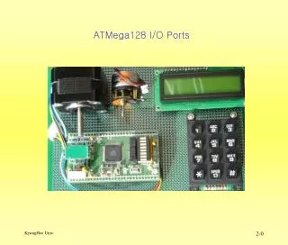
ATMega128 I/O Ports. ATMega128 I/O Ports. 6 개의 8 비트 양방향 병렬 I/O 포트 (PORTA~F) 1 개의 5 비트 양방향 병렬 I/O 포트 (PORTG) 각 PORT 별 3 개 I/O 레지스터 영역 DDR(Data Direct Register) : 입출력 방향 결정 PORT(Data Register) : 데이터 출력 PORT PIN(Port Input Pins Register) : 포트의 입력 핀 Rg

E N D
ATMega128 I/O Ports • 6개의 8비트 양방향 병렬 I/O 포트(PORTA~F) • 1개의 5비트 양방향 병렬 I/O 포트(PORTG) • 각 PORT별 3개 I/O 레지스터 영역 • DDR(Data Direct Register) : 입출력 방향 결정 • PORT(Data Register) : 데이터 출력 PORT • PIN(Port Input Pins Register) : 포트의 입력 핀 Rg • DDR, PORT : 읽기/쓰기 가능, PIN : 읽기만 가능
ATMega128 I/O Ports의 특징 • 특징 • 최대 40mA 구동 전류 • LED 1개 구동 가능 • 선택 가능한 Pull Up 저항 내장 • 20K – 100K Ohm • Vcc, GND 사이에 입력단보호 Diode 내장 • Read-Modified-Write Cycle 지원 • 다른 pin의 영향을 주지 않고 한 port 핀의 방향을 바꿀 수 있음 • SBI 나 CBI instruction 사용
ATMega128 I/O Ports • 모든 Port는 다음과같은 특성을 갖는다. • Bit-selectable pull-up resistors • Bit-selectable tri-state outputs • Schmitt trigger input • Synchronized to the system clock : 입력신호의 안정성에 기여(Pin Read Operation 시 1.5Cycle 이전에 Pin 신호가 안정화 되어야 함) • 같은 port에 write한 다음 바로 read 방지 nop instruction 필요 : __no_operation(); • Symmetrical DC drive capability
ATMega128 I/O Ports • I/O Port input structure • Protection diodes • Programmable pull-up resistor pull-up resistor port pin
AVR port architecture DDRx pull-up resistor PORTx port pin schmitt trigger buffer analog switch PINx
IO Port Register • Port A-G 동일
SFIOR: Special Function IO Reg. • PUD • PUD Set 1 : Pull-Up Diable • DDxn = 0, PORTxn = 1로 설정되어도 이 bit가 우선함
Port A 부가 기능 • 외부 memory 확장 • 하위 8bit address와 8bit data • ALE 신호
Port B 부가 기능 • Timer/Counter Output • SPI Bus Interface
Port C 부가 기능 • 외부 memory 확장 • 상위 8bit address
Port D 부가 기능 • Timer/Counter Input • USART Interface • External Interrupt • TWI Serial Interface
Port E 부가 기능 • External Interrupt • Timer/Counter Input and Output • Analog Comparator • UART Interface
Port F 부가 기능 • ADC Input • JTAG interface
Port G 부가 기능 • RTC Oscillator • External memory interface • ALE/RD/WR
ATMega128 I/O Ports • Port 이용 프로그램 작성시 고려 할 점 • Input pins 1.5 clock cycle delay를 갖는다. • Read Operation을 실행하기 1.5 clock cycle 전에 Input Pin의 상태가 안정 되어야 한다. • I/O 관련 프로그램을 보다 • Transportable, • Readable, • More bug free 하게 작성 하기 위한 예 TIMSK = b01000000; 위와 예 보다 아래 예가 보다 적정 하다. TIMSK |= (1<<TOIE0);
AVR I/O port programming • iom128.h File에 Port 사용에 관련된 정의가 있다. • 예 /*Data Register, Port B */ #define PORTB _SFR_IO8(0x18) …… …… /*Port B Data Register – PORTB */ #define PB7 7 #define PB6 6 #define PB5 5 #define PB4 4 #define PB3 3 #define PB2 2 #define PB1 1 #define PB0 0
AVR I/O port programming • #define 은 아래와 같이 이해하기 쉬운 프로그램 작성을 가능하게 한다. • 예 PORTB = 0x05; DDRB = 0x0A; SPCR = (1<<SPE) | (1<<MSTR); DDRB |= (1<<DDB2) | (1<<DDB0); temp0 = PINB;
AVR I/O port programming • AND, OR, XOR 논리 연산을 이용한 Bit Operation • 예 //toggle bit 5 PORTB = PORTB ^ 0x20; // invert PORTB ^= 0x20; // invert again another way //set bits 7 and 2, don't bother others PORTB = PORTB | 0x84; PORTB |= (1<<PB7)|(1<<PB2) ; //shorter, more portable //clear bit 0 and 1, but nothing else PORTB = PORTB & 0xfc; PORTB &= ~((1<<PB0)|(1<<PB1)); //more portable
AVR I/O port programming • Mask를 사용 하여 개별 Bit 값을 알 수 있다. • 예 //Port D 의 D0 bit 가 1 인가를 Test 한다. if(PIND & 0x01){take_some_action();} 윗 예에서 0x01을 mask 라 한다. 아래 예에서는 D5 Bit가 0 인가를 Test 한다. //looking for bit 5 of port B to be a zero if(~PIND & 0x20){take_action();} • avr-libc functionbit_is_set() 과 bit_is_clear() 를 사용 하여 아래와 같이 프로그램 할 수도 있다. if (bit_is_set(PINC, PC2) {return 0;} while (bit_is_clear(SPSR,SPIF)) {}
AVR I/O port programming 예 #include <avr/io.h> void port_init(void){ PORTA = 0x00; // DDRA = 0x00; // Input Port PORTF = 0x00; DDRF = 0xff; // Output Port } int main(void){ port_init(); // PINA 의 상태을 PORTF에 출력 한다. while(1){ PORTF = PINA; } }
AVR I/O port interfacing • Pull-ups 기능은 Switch를 외부 저항 없이 Input Port에 Interface 할 수 있게 한다. 그러나 Leakage current 가 증가 할 우려가 있다. • 외부 조건(정전기, 부하에 의한 고전압 발생 등)에 대한 I/O Port protection에 대한 고려가 필요 함. • Led Drive Circuits • 적절한 Current Limit Resistors의 선택이 필요함. • Motor or relay drive circuits • Inductive에 의한 고전압을 제거 하는 Diode 필요 • 5V to 3.3V or 3.3V to 5V interfacing • Resistor and protection diode • Interface Chip : 74LVC244, TXB0108 등