Basic Rendering Techniques
Basic Rendering Techniques. Scientific Visualization V106.03. Rendering and Shading Techniques. Rendering produces a finished image. The closer the rendering is to create a natural scene, the more complex it is, and the longer it takes to render the scene.

Basic Rendering Techniques
E N D
Presentation Transcript
Basic Rendering Techniques Scientific Visualization V106.03
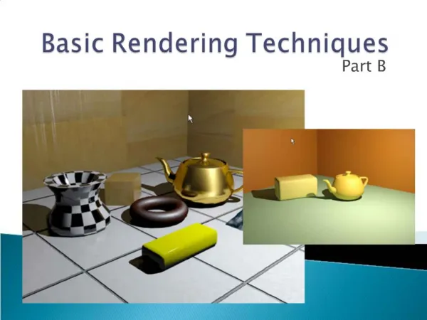
Rendering and Shading Techniques • Rendering produces a finished image. • The closer the rendering is to create a natural scene, the more complex it is, and the longer it takes to render the scene. • Rendering the scene to a file may include such things as the background, output size, compression, file type, and output path. • Rendering previews are small and quick to check your scene prior to doing a full render.
Texture Mapping • The term texture in 3D computer graphics refers to image patterns rather than the “feel” of materials. • The most basic type of texture is a 2D picture (often saved as a .jpeg, .bmp, or .tga file), which is applied to an object.
Texture Mapping • Surfaces may have single colors or they may have multiple color patterns, which are commonly referred to as textures. • For example: wood has a characteristic appearance because of its varying color patterns. • Even materials like metals which seen to be one color, when closely examined, reveal varying shades and colors mixed in random patterns.
Texture Mapping • Opacity maps control whether a material is opaque, transparent, or translucent. • Adding textures to the object is an extremely important part of making objects look real.
Texture Mapping • Textures may be acquired in different ways. • Most 3D programs come with libraries where you can select various materials and patterns. • Typically, 3D programs allow materials to be added to the library
Acquiring Materials • New materials can be made by combining existing library selections and sometimes using “mixing formulas” (blending) provided by other 3D artist. • There are graphic programs designed for creating 2D textures (such as CorelDraw or Photoshop) that can be found on the Internet or through software suppliers.
UV Space • UV mapping is a way of trying to solve the distortion problems that occur when applying image maps (textures) to complex surfaces. • Many 3D graphic programs allow texture image scaling and placement controls.
UV Space • U represents the horizontal component of an image. It corresponds to the X axis dimension in 2D coordinate space. • V represents the vertical component of an image. It corresponds to the Y axis dimension in 2D coordinate space. • W represents the z axis in 3D coordinate space.
UV Space • By applying UV scaling and placement restraints, the most appropriate fit of the image can be obtained. • By manipulating UV controls, it is also possible to apply textures to parts of surfaces as well as an entire surface. • Tiling allows pattern to be repeated, much like tiles on a floor.
Bump Mapping • Bump maps simulate the roughness of surfaces even though the surfaces are perfectly flat. • Bump maps make an object appear to have a bumpy or irregular surface. This is possible because of higher areas are light and lower areas are dark. • Surface roughness might include the unevenness of a brick surface, the weave of a fabric, or the bumpiness of an orange.
Bump Mapping • The process of creating artificial roughness takes less computing power than actually dividing the surface into large numbers of polygons and moving the vertices of those polygons up or down to create a real roughness. • Settings allow the user to determining the height and depth of bumps. • Bump maps can be produced by photographing surfaces, scanning images and actual materials, or by using software programs to draw patterns in grayscale.
Lighting • 3D programs have some type of default lighting, which can be changed to create a more realistic appearance. • There are several common types of CG (computer graphics) lights.