Download
1 / 19
200 likes | 516 Vues
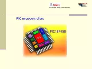
Embedded System Spring, 2011 Lecture 4: The PIC Microcontrollers Eng. Wazen M. Shbair. Today’s Lecture. The WREG Register The PIC File Register. The WREG Register. D7. D6. D5. D4. D3. D2. D1. D0. Many registers for arithmetic and logic operation.

E N D
Embedded SystemSpring, 2011Lecture 4: The PIC MicrocontrollersEng. Wazen M. Shbair
Today’s Lecture • The WREG Register • The PIC File Register IUG- Embedded System
The WREG Register D7 D6 D5 D4 D3 D2 D1 D0 • Many registers for arithmetic and logic operation. • The WREG (WORking Register) Register is one of the most widely used registers of the PIC • 8-bit register any data larger than 8 bits must be broken into 8-bits chunks before it is processed. • There is only one . 3-3
MOVLW • Moves 8-bit data into WREG • MOVLW k; move literal value k into WREG • Example • MOVLW 25H • MOVLW A5H • Is the following code correct? • MOVLW 9H • MOVLW A23H 1-4
ADDLW 0 0 0 0 0 1 0 1 0 1 0 0 1 0 0 0 • ADDLW k; Add literal value k to WREG (k +WREG) • Example: • MOVLW 12H • ADDLW 16H 1-5
The WREG Register • When programming the WREG of PIC , the following points should be noted: • Values can be loaded directly into the WREG. • If values 0 to F are moved into an 8-bit register such as WREG, the rest of the bits are assumed to be all zeros. • Moving a value larger than 255 (FF in hex) into the WREG register will truncate the upper byte and cause a warning in the .err file.
The WREG Register • MOVLW 7F2H; Illegal , becomes F2H • MOVLW 456H ; Illegal, becomes 56H • MOVLW 60A5H; Illegal, becomes A5H
The PIC File Register • It is the data memory. • Read/Write Static RAM • Used for data storage, scratch pad and registers for internal use and function • 8-bit width
Register File Concept Data Memory (Register File) • Register File Concept: All of data memory is part of the register file, so any location in data memory may be operated on directly • All peripherals are mapped into data memory as a series of registers • Orthogonal Instruction Set: ALL instructions can operate on ANY data memory location w f 07h ALU 08h 09h 0Ah 0Bh Data Bus d w f 0Ch 0Dh 0Eh 0Fh 10h WREG Decoded Instruction from Program Memory: Opcode d a Address Arithmetic/Logic Function to be Performed Address of Second Source Operand Result Destination
Special Function Registers • Dedicated to specific functions such as ALU status, timers, serial communication, I/O ports, ADC,… • The function of each SFR is fixed by the CPU designer at the time of design • it is used for control of the microcontroller or peripheral • 8-bit registers • Their numbers varies from one chip to another. 1-11
General Purpose RAM • Group of RAM locations • 8-bit registers • Larger than SFR • Difficult to manage them by using Assembly language • Easier to handle them by C Compiler. • The microchip website provides the data RAM size, which is the same as GPR size.
GP RAM vs. EEPROM in PIC chips • GPRs are used by the CPU for internal data storage. • EEPROM are considered as add-on memory that one can add externally to the ship. • So PIC chip may have zero byte of EEPROM data memory, but impossible for a PIC have zero size for the file register.
File Register and access bank in the PIC18 • The PIC18 Family can have a max. of 4096 Bytes. • The File Register • has addresses of 000- FFFH • divided into 256-byte banks • Max. 16 banks (How?) • At least there is one bank • Known as default access bank. • Bank switching is a method used to access all the banks. 1-16
Access bank in the PIC18 • It is 256-Byte bank. • Divided into equal two discontinuous sections (each 128 B). • GP RAM, from 0 to 7FH • SFR, from F80H to FFFH 1-17
References • Jie Hu , ECE692 Embedded Computing Systems , Fall 2010. • PIC Microcontroller And Embedded Systems: using Assembly and C for PIC 18, M. Mazidi, R. McKinlay and D. Causey, Prentice Fall, 2008. • Eng. Husam Alzaq, Embedded System Course, IUG, 2010 IUG- Embedded System 19