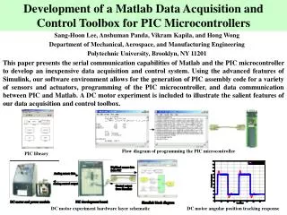
Understanding PIC Microcontrollers: Design Flow, Bus Structure, and Instruction Pipelining
This comprehensive study guide covers essential concepts of PIC microcontrollers, focusing on design flow, the workings of C code and assembly language, and interfacing with hardware. Topics include bus structure—covering unidirectional and bidirectional data and address buses, the significance of bus width, and types of buffers. Additionally, the memory addressing process is explored, including MAR and decoder mechanisms. Finally, it introduces pipelining in instruction execution, detailing the fetch and decode stages, allowing for efficient processing in microcontroller systems.

Understanding PIC Microcontrollers: Design Flow, Bus Structure, and Instruction Pipelining
E N D
Presentation Transcript
STUDY OF PIC MICROCONTROLLERS.
Design Flow C CODE Compiler Assembly Code Assembler Hex File Chip Programming
I/O Device Unidirectional Address Bus Bidirectional Data Bus Processor Control Signals Memory Basic Micro Computer BUS Structure • Bus is a group of lines carrying digital Information • Bus width indicates number of bit lines • Two Types of Buses in any Processor: • Data Bus (eg: 8 bit processor has 8 bit data bus. Eg: PIC) • Address Bus (Defines the memory size) Bus is driven by buffers from different devices, processor &memory. Ques: How to arbitrate between different devices that want to access the bus at the same time?
TRISTATE BUFFERS Regular BUFFERS INTRODUCTION TO MEMORIES
Memory Addressing and Access 1)Register addresses : 00,01, 10, 11 2)Active Low Wr and Read enable signal comes from control unit 3) Additional chip select also provided if more than one set of memory registers available Data Bus Processor Input Buffer WR A1 A0 00 Register 0 01 Memory Address Decoder Memory Address Register [MAR] Register 1 10 Register 2 10 Register 3 Output Buffer • Questions: • For a memory of 1 K byte and word size of 8 bits • What is the width of MAR • How many address lines come out of the decoder • What is the register width • What is the input/output data width ??? • What is the size of processor address bus • What is the size of the processor data bus RD
DATA Transfer Unit Main Memory location
DATA Transfer Unit Main Memory location along with MAR and Decoder
DATA Transfer Unit WW : work register write (Data bus to register) WR: Work register read (reg to bus) WCLK: clock Memory with Working Register
ENHANCED DTU (With Program Counter) Program memory is separate from data memory OPCODE= instruction codes.
SYSTEM CLOCK and PIPELINING Instruction execution takes place in 2 stages , each stage needs 4 clock cycles. Instruction Fetch and Instruction Decode Fetch: clock1: Increment PC (PC <= PC+1) (phase 1) clock 2,3: idle. Clock 4: Instruction loaded in to IR Decode: clock 1 : Instruction decode clock 2 : Fetch data from register or port clock 3 :Operations carried out with data Clock 4 :Results loaded back to destination FETCH AND DECODE ARE INDEPENDENT. HENCE THEY CAN BE DONE IN PARALLEL. THIS IS CALLED PIPELINING. This is a 2 stage pipelining concept.