Introduction to Microcontrollers: Key Concepts and Features
Discover the fundamentals of microcontrollers, including embedded design, processor architecture, memory types, CISC vs. RISC, and key features such as I/O ports, timers, and peripherals. Explore the applications and examples of 8-bit microcontrollers.


Introduction to Microcontrollers: Key Concepts and Features
E N D
Presentation Transcript
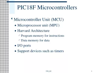
An embedded microcontroller is a chip which is a computer processor with all it’s support functions (clocking and reset), memory, and i/O built into the device. Power dist Control store Reset control Clock and timing RAM Microcontroller block diagram
types of microcontrollers • Embedded • All the hardware required to run the application is provided on the chip. typically: power, reset, clock, memory and IO. • External memory • some microcontrollers allow the connection of external memory.
Processor Architecture • Harvard and Princeton • US govt asked for computer to be used with naval shell distance for varying elevations and environmental conditions. • Princeton provided ‘Von Neumann’ architecture where common memory space are used for storing program and data. Memory unit is responsible for arbitrary access to memory space between reading instructions and passing data back and forth with processor and its internal registers. • Advantages: simple memory interfacing and management. • Harvard proposes a design that used separate memory banks for program storage, the processor stack, and variable RAM. • Advantage: execute instruction in fewer cycles than Von Neumann.
Princeton architecture block diagram program ROM instruction decode Processor and built-in registers Data memory interface unit Variable RAM Add Ctrl Stack RAM
Harvard architecture block diagram Data program ROM instruction decode Variable RAM Add Ctrl PC Stack Processor and built-in registers Data Add Ctrl
CISC versus RISC • RISC stands for “Reduced Instruction Set Computers”. Instructions are as bare a minimum as possible to allow users to design their own operations. • CISC stands for “Complex Instruction Set Computers”. Large number of instructions, each carrying out a different permutation of the same operation.
Microcontroller memory types • Control store • program memory or firmware. this memory space is the maximum size of the application that can be loaded into the microcontroller and that the application also includes all the low-level code and device interface necessary to execute an application. • nonvolatile • 8051 has 5 different types of control store : none, mask ROM, PROM, EPROM and EEPROM/Flash
Variable area (RAM) • 4 types variable data storage: bits, registers, variable RAM, PC stack. • in 8051 they are implemented as SRAM. • program counter stack • part of the RAM. • LIFO memory. • must be initialized by the starting address of the stack area.
Hardware interface registers (I/O space) • could be memory mapped or IO mapped. • mostly in variable memory space. • IO in Princeton architecture memory mapped IO separate IO space program ROM program ROM IO registers IO registers variable RAM variable RAM Stack Counter Stack Counter
IO in Harvard architecture IO registers in program ROM IO registers in register space IO registers in separate space program ROM registers space program ROM registers space program ROM register space IO registers IO registers IO registers
Microcontroller features • Clock/Oscillator • IO pins • interrupts • timers • Peripherals • ADC inputs • DAC outputs • PWM outputs Basic features
Comparing µC with µP • General-purpose microprocessors contains • No RAM • No ROM • No I/O ports • Microcontroller has • CPU (microprocessor) • RAM • ROM • I/O ports • Timer • ADC and other peripherals • Have the advantage of versatility on the amount of RAM, ROM, and I/O ports • The fixed amount of on-chip ROM, RAM, and number of I/O ports and less computing power; suitable for very specific purpose with much less cost.
Applications • Home • Appliances, intercom, telephones, security systems, garage door openers, answering machines, fax machines, TVs, cable TV tuner, VCR, camcorder, remote controls, video games, cellular phones, musical instruments, sewing machines, lighting control, paging, camera, pinball machines, toys, exercise equipment. • Office • Telephones, security systems, fax machines, microwave, copier, laser printer, color printer, paging. • Auto • Navigation system, engine control, air bag, ABS, instrumentation, security system, transmission control, entertainment, climate control, cellular phone, keyless entry.
Examples of 8-bit µC • Motorola’s 6811 • Intel’s 8051 • Zilog’s Z8 • Microchip’s PIC The 8051 family has the largest number of diversified (multiple source) suppliers: • Intel (original) • Atmel • Philips/Signetics • AMD • Infineon (formerly Siemens) • Matra • Dallas Semiconductor/Maxim
8051 µC features • Intel introduced 8051, referred as MCS-51, in 1981 • The 8051 is an 8-bit processor • The CPU can work on only 8 bits of data at a time • 1 to 16 MHz clock • The 8051 has • 128 bytes of RAM • 4K bytes of on-chip ROM • Two timers • One serial port • Four I/O ports, each 8 bits wide • 2 external and 3 internal interrupt sources
contd. • 8051 instruction cycle consists of 12 clock cycles. • Application should be run using slower clock speed to reduce power consumption. • Dallas version of 8051 is 87C51 has EPROM as control store and CMOS device: • 24Mhz • 12 cycle per instruction • 4Kbyte of Control stote • 128 bytes of RAM • 32 I/O lines • Two 8/16-bit times • Multiple internal and external interrupts sources • Programmable serial ports • Interface upto 128Kbytes of external memory
8051 Block Diagram Frequency Reference counters oscillator 4K Prog Memory 2 16-bit timers/ counter 128 B RAM 8051 CPU 64K bus expansion control I/O ports Serial port/ UART interrupt interrupt control Ports/IO/ ADD/Data bus Tx Rx
8051 memory-register map FFFF FFFF FFFF up to 64 KB of external EPROM/ ROM up to 60 KB of external ROM/ EPROM up to 64 KB of external RAM SF = Special Function 00F8 21 SF registers 128 KB internal RAM 1000 or and 0080 007F 0FFF 4 KB of internal ROM/ EPROM 0000 0000 0000 0000 program memory RAM/data memory
128 bytes internal RAM 7F (80) scratch pad TCON 88H 8F 88 PCON 87H F0H F7 F0 B 2F (16) bit/byte addressable DPH 83H ACC E0H E7 E0 DPL 82H PSW D0H D7 D0 IP B8H BF B8 SP 81H P3 B0H B7 B0 P0 80H 87 80 1F (8) 8-bit registers bank 3 IE A8H AF A8 A0H A7 A0 P2 SBUF PSW 99H CY AC F0 RS1 RS0 OV P 17 (8) 8-bit registers bank 2 4 register banks 98H 9F 98 SCON CY – carry flag P1 90H 97 90 AC – auxiliary carry F0 – general purpose indicator 0F (8) 8-bit registers bank 1 TH1 8DH RS1 – register bank selector bit 1 TH0 8CH RS0 – register bank selector bit 0 TL1 8BH 08 07 (8) 8-bit registers bank 0 8AH TL0 TMOD 89H
About RAM • 128 bytes of internal RAM (00H to 7FH)is general R/W storage. • Part of this RAM is used as general purpose registers. • 21 Special-Function Registers (SFR) which are not part of 128 bytes of RAM at 80H to F8H locations of the RAM space. • 64 KB External RAM can be used fully in addition to 128 internal RAM. • Although 8051 normally operates with separate program and data memory space, there are applications where it can be used as one 64 KB of memory. When this is done, 8051 can input a block of data through its serial communication port, load it into memory, and then execute that data as a program.
SFRs are accessed as if they were normal Internal RAM. The only difference is that Internal RAM is from address 00h through 7Fh whereas SFR registers exist in the address range of 80h through F8h. • B register is used during multiply and divide operations as to hold higher 8-bit source. Otherwise it can used as a simple scratch-pad register. • ACC and PSW are like microprocessor’s accumulator and flag. PSW does not have a zero flag. RS1 and RS0 indicates the current register bank. • DPH and DPL is used as 2-byte data pointer DTPR when addressing external memory. Can be used as 8-bit or 16 bit memory pointers. • SP incremented just before data is stored by using push or call instruction or the interrupt. 8051 SP initialized to 07H on reset. This means first data put on the stack is loaded into memory location 08H. • The 8051 has four I/O ports of 8 bits, for a total of 32 I/O lines. P0,P1,P2 and P3. • PCON is power control register. Can put mp into hibernation and conserve power.
About Program memory • if more program memory is needed, internal 4 KB memory can be expanded by an additional 60 KB, giving a full 64 KB of program memory space. • if EA (active low) is asserted, the 8051 does not use the internal 4K ROM. The external memory must start from location 0000H.
Clock/Oscillator • Clock and communication requirement • Ceramic or crystal? • State=2 pulses • Machine cycle=6 states • Instruction cycle=1/2/4 MC
Timers/counters • Event detection, timed control signal generation, counter etc. • Reads from or written to by the processor and is given by some constant frequency source. Generates an interrupt at the overflow. Run by µC clock or external clock.
Timer/counter contd.. • A machine cycle instruction lasts for 12 quartz oscillator periods, which means that by embedding quartz with oscillator frequency of 12MHz, a number stored in the timer register will be changed million times per second, i.e. each microsecond. • 2 timers/counters called T0 and T1 • If the timer contains for example number 1000 (decimal), then the TH0 register (high byte) will contain the number 3, while the TL0 register (low byte) will contain decimal number 232. • Formula: TH0 × 256 + TL0 = Tso, 3 × 256 + 232 = 1000 TH0 = 1000/256 = 3 (00000011) TL0 = 1000 – 3x256 = 232 (11101000)
Timer/counter contd.. • The largest value it can store is 65 535 • In case of exceeding this value, the timer will be automatically cleared and counting starts from 0. This condition is called an overflow.
TMOD Register (Timer Mode) • There are 4 operational modes. • The low 4 bits (bit0 - bit3) refer to the timer 0, while the high 4 bits (bit4 - bit7) refer to the timer 1. • GATE1 enables and disables Timer 1 by means of a signal brought to the INT1 pin (P3.3): • 1 - Timer 1 operates only if the INT1 bit is set. • 0 - Timer 1 operates regardless of the logic state of the INT1 bit. • C/T1 selects pulses to be counted up by the timer/counter 1: • 1 - Timer counts pulses brought to the T1 pin (P3.5). • 0 - Timer counts pulses from internal oscillator. • T1M1,T1M0 These two bits select the operational mode of the Timer 1.
GATE0 enables and disables Timer 1 using a signal brought to the INT0 pin (P3.2): 1 - Timer 0 operates only if the INT0 bit is set. 0 - Timer 0 operates regardless of the logic state of the INT0 bit. C/T0 selects pulses to be counted up by the timer/counter 0: 1 - Timer counts pulses brought to the T0 pin (P3.4). 0 - Timer counts pulses from internal oscillator. T0M1,T0M0 These two bits select the operational mode of the Timer 0.
Timer 0 in mode 0 (13-bit timer): • This mode configures timer 0 as a 13-bit timer which consists of all 8 bits of TH0 and the lower 5 bits of TL0. As a result, the Timer 0 uses only 13 of 16 bits. Each coming pulse causes the lower register bits to change their states. After receiving 32 pulses, this register is loaded and automatically cleared, while the higher byte (TH0) is incremented by 1. This process is repeated until registers count up 8192 pulses. After that, both registers are cleared and counting starts from 0.
Timer 0 in mode 1 (16-bit timer) • Mode 1 configures timer 0 as a 16-bit timer comprising all the bits of both registers TH0 and TL0. That's why this is one of the most commonly used modes. Timer operates in the same way as in mode 0, with difference that the registers count up to 65 536 as allowable by the 16 bits.
Timer 0 in mode 2 (Auto-Reload Timer) • Mode 2 configures timer 0 as an 8-bit timer. Actually, timer 0 uses only one 8-bit register for counting and never counts from 0, but from an arbitrary value (0-255) stored in another (TH0) register.
Timer 0 in Mode 3 (Split Timer) • Mode 3 configures timer 0 so that registers TL0 and TH0 operate as separate 8-bit timers. In other words, the 16-bit timer consisting of two registers TH0 and TL0 is split into two independent 8-bit timers. This mode is provided for applications requiring an additional 8-bit timer or counter. The TL0 timer turns into timer 0, while the TH0 timer turns into timer 1. In addition, all the control bits of 16-bit Timer 1 (consisting of the TH1 and TL1 register), now control the 8-bit Timer 1. Thus, the operation 16 bit timer 1 is restricted when timer 0 is in mode 3.
Timer Control (TCON) Register • Only 4 bits of this register are used for this purpose, while rest of them is used for interrupt control. • TF1 bit is automatically set on the Timer 1 overflow. • TR1 bit enables the Timer 1. • 1 - Timer 1 is enabled. • 0 - Timer 1 is disabled. • TF0 bit is automatically set on the Timer 0 overflow. • TR0 bit enables the timer 0. • 1 - Timer 0 is enabled. • 0 - Timer 0 is disabled.
How to use the Timer 0 ? • the timer 0 operates in mode 1 and counts pulses generated by internal clock the frequency of which is equal to 1/12 the quartz frequency.
Timer 0 Overflow Detection • When it occurrs, the TF0 bit of the TCON register will be automatically set. The state of this bit can be constantly checked from within the program or by enabling an interrupt which will stop the main program execution when this bit is set. • a program delay of 0.05 seconds (50 000 machine cycles).
IO ports • All four 8 bit ports are bidirectional. • Port latch (D-type FF) allows u to store data going out of the port or coming into the port. The latch can be set by data on the data bus or at the port pin. Also the latch can place data on the mc bus or send it to the port pin. However, port pins may have different value than port latches. • When 1s are written to port, pins are pulled high (or floats) by the internal pull-ups and can be used as inputs. • In order to configure a microcontroller pin as an output, it is necessary to apply a logic zero (0) to appropriate I/O port bit. In this case, voltage level on appropriate pin will be 0.
Port 0 • The Port 1 is a general purpose input/output port which can be used for a variety of interfacing tasks. • To use the pins of port 0 as both input and output each pin must be connected externally to a 10KΩ pull-up resistor.
Dual role of P0 • Port 0 and 2 together can be used to address the external memory. Port 0 can also be used to exchange data from the external port. accessing 64K bytes of external memory, it needs a path for the 16 bits of the address. P0 gives lower Byte of Address.
Port 1 • This port does not need any pull-up resistors since it already has pull-up resistors internally. • If port 1 is configured as an output port, to make it an input port again, it must programmed as such by writing 1 to all its bits. • Upon reset, port I is configured as an input port. • In the following code, port 1 is configured first as an input port by writing 1 s to it, then data is received from that port and saved in R7, R6, and R5.
Port 2 • It can be used as input or output. • Internal pull-up resistor. • Upon reset, port 2 is configured as an input port. • Alternate use • provide higher byte address when external memory is connected.
Port 3 • Port 3 can be used as input or output. On Reset input port. • Has internal pull-up resistors. • Alternate use • providing some extremely important signals such as interrupts, serial I/O, timer/counter and read/write control for external memory.
Interrupts • Two SFRs controls the function of interrupts in 8051 microcontroller. • IE, Responsible for disable/enable the function. • IP, Responsible for priority assignment: • The priority list offers 3 levels of interrupt priority: • Reset! The absolute master. When a reset request arrives, everything is stopped and the microcontroller restarts. • Interrupt priority 1 can be disabled by Reset only. • Interrupt priority 0 can be disabled by both Reset and interrupt priority 1.
EA - global interrupt enable/disable: • 0 - disables all interrupt requests. 1 - enables all individual interrupt requests. • ES - enables or disables serial interrupt: • 0 - UART system cannot generate an interrupt. 1 - UART system enables an interrupt. • ET1 - bit enables or disables Timer 1 interrupt: • 0 - Timer 1 cannot generate an interrupt. 1 - Timer 1 enables an interrupt. • EX1 - bit enables or disables external 1 interrupt: • 0 - change of the pin INT0 logic state cannot generate an interrupt. • 1 - enables an external interrupt on the pin INT0 state change. • ET0 - bit enables or disables timer 0 interrupt: • 0 - Timer 0 cannot generate an interrupt. 1 - enables timer 0 interrupt. • EX0 - bit enables or disables external 0 interrupt: • 0 - change of the INT1 pin logic state cannot generate an interrupt. • 1 - enables an external interrupt on the pin INT1 state change. • *bit6 is not implemented. • * ET2 is reserved for future use.
If an interrupt of higher priority arrives while an interrupt is in progress, it will be immediately stopped and the higher priority interrupt will be executed first. If the both interrupt requests, at the same priority level, occur one after another, the one which came later has to wait until routine being in progress ends. If two interrupt requests, at different priority levels, arrive at the same time then the higher priority interrupt is serviced first. If two interrupt requests of equal priority arrive at the same time then the interrupt to be serviced is selected according to the following priority list: External interrupt INT0, i.e. IE0 Timer 0 interrupt, i.e. TF0 External Interrupt INT1, i.e. IE1 Timer 1 interrupt, i.e. TF1 Serial Communication Interrupt, i.e. RI, TI Interrupt Priority
PS - Serial Port Interrupt priority bit • Priority 0 or Priority 1 • PT1 - Timer 1 interrupt priority • Priority 0 or Priority 1 • PX1 - External Interrupt INT1 priority • Priority 0 or Priority 1 • PT0 - Timer 0 Interrupt Priority • Priority 0 or Priority 1 • PX0 - External Interrupt INT0 Priority • Priority 0 or Priority 1 • Bit7 and bit6 are not implemented. PT2 is reserved for future use.
Handling Interrupt • When an interrupt request arrives the following occurs: • Instruction in progress is ended. • The address of the next instruction to execute is pushed on the stack. • Depending on which interrupt is requested, one of 5 vectors (addresses) is written to the program counter in accordance to the table below: • When an interrupt routine is executed, the address of the next instruction to execute is poped from the stack to the program counter and interrupted program resumes operation from where it left off.