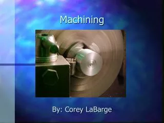
Generative Machining
KP3213 CAD/CAM. Generative Machining. The Design and Manufacturing Process. Design. Analyse. Manufacture. Part models Assembly models. FEA Mechanisms. CNC machining. CNC Machining. Computer Numerical Control uses programmed instructions to drive the machine tool. CNC program

Generative Machining
E N D
Presentation Transcript
KP3213 CAD/CAM Generative Machining
The Design and Manufacturing Process Design Analyse Manufacture Part models Assembly models FEA Mechanisms CNC machining
CNC Machining • Computer Numerical Control uses programmed instructions to drive the machine tool CNC program (computer file or paper tape) machine control unit (MCU) machine tool
Numerical Control Elements • MCU – Machine Control Unit • Every NC machine tool is fitted with MCU which perform various controlling function • May be house separately • Looks like a computer with display panel of small size, number of control buttons and kerboard • This control unit controls the motion of cutting tool, spindle speeds, feed rate, tool changes, fluids application and etc. • Part Program • NC Tooling
NC Machine Tools • Suitable in the industry due to the following • Parts with complex contours, conventional could not machine • For small lot production, even for single or prototype • For job acquiring high accuracy • For jobs requiring many set up and setups are expensive • For parts that are subjected to frequent changes • The inspection costs is a significant portion of the total manufacturing costs
Advantage of NC • Parts produced in less time, thus cheaper • Higher accuracy • Less scrap due to no operator involvement (during operation, except set up) • Minimum expensive fixture or jigs needed • Inspection time is reduced • Form are not needed • Lead time reduced • CNC machine can perform many operations on one machine • Set up are reduced • Machine times and costs are more predictable • Etc
Limitation of NC • Costs of machine • Costs and skill of people • Special training needed • High maintenance, spares and wages
Types of CNC Machines • Milling machines (prismatic parts) • Lathes (rotational parts) • Laser cutters (flat plate) • EDM, Electric Discharge Machine (complex cutting) • Punches (plate, sheet metal) • Etc.
CNC Machining Centres • Machining centres typically include: • automatic tool changer • automatic workpart positioning • pallet shuttle • multiple spindles
Machining Applications • Final machined part • starting with raw stock material • suitable for small production quantities • Machined features on part • starting with near net shape part, e.g., cast or forged part • example: engine block • Prototypes of part • Tooling and molds to make the part
Elements of CNC Programming • Tool selection, feeds and speeds • Cutter path specification • interpolation • tool offset calculations • tool interference (gouge avoidance) • Generation of NC instructions
Tool Offset coordinates of this point need to be calculated tool tool offset workpart tool path
potential interference Tool Interference(Gouging) surface being machined
part geometry (drawing, CAD) tool paths, feeds and speeds NC program The NC Programming Cycle
CNC Hardware Basics • Spindle design • To get best finishes, rate of material removal, radial or axial force to be taken care off • Drives • Spindle drive – DC motor generally used • Feed drive – DC servomotors, Brushless DC Servomotors, AC servomotor, Stepper motor, Linear motor • Actuation system • Feedback device • To provide accurate control to the movement of the axes • Axes-Standard • X, Y and Z axes their direction
CNC Tooling Cutting tool material • High Speed Steel (HSS) • Cemented Carbide • Coated Carbide • Ceramics
I-DEAS Generative Machining Definitions • Setup assembly • part, fixtures, clamps, etc. • Job • all operations required to make part • there may be more than one job defined for a part • OpGroups • set of machining operations for a specific feature, e.g. a pocket • Operations • specific operations, e.g., finish machining
I-DEAS Generative Machining Process • Load part model • Define setup assembly (fixtures, clamps, etc.) • Create Job For each feature: • Create OpGroup • Define Operations
Typical Process For each operation: • Specify operation • Select tool • Specify feeds and speeds • Specify cutting patterns, etc.
Program Generation • I-DEAS generates a neutral Cutter Location Data file • The CL data file specifies the complete CNC program • In I-DEAS, the CL instructions are based on the APT language for programming NC machines
Sample CL DATA file description feeds and speeds tool definition PARTNO/'mold' UNITS/MM PPRINT/'OPERATION CATEGORY & TYPE: Milling Copy Mill' PPRINT/'OPERATION NUMBER & NAME: Operation-2' PPRINT/'TOOL IDENTIFIER: 25mm ball mill' PPRINT/'POST TOOL ID: 0' PPRINT/'TOOL DESCRIPTION: ' PPRINT/'TOOL STATION NUMBER: 2' MODE/MILL MULTAX/OFF LOADTL/0, IN, 2, LENGTH, 0.000000, OSETNO, 0 CUTTER/25.000000, 12.500000 LINTOL/0.050000 SPINDL/2200.000, RPM, CLW FEDRAT/460.000000, MMPM RAPID GOTO/-17.482028, -26.300947, 175.888264 RAPID GOTO/-17.482028, -26.300947, 90.500001 FEDRAT/460.000000, MMPM COOLNT/FLOOD GOTO/-11.799326, -28.654799, 87.500001 GOTO/-11.764249, -28.654799, 86.205800 GOTO/-11.653224, -28.654799, 84.876054 GOTO/-11.460460, -28.654799, 83.515977 GOTO/-11.179711, -28.654799, 82.131884 GOTO/-10.806236, -28.654799, 80.730904 Cutter path data
Program Simulation • I-DEAS tool paths can be simulated graphically • This assists in debugging before any actual cutting is done
G-Code Generation • CNC machines require programs in G-code format • G-code is a low-level NC programming language • There are variations between machines, so machine-specific post-processors are used • I-DEAS uses a post-processor to generate G-code from the CL Data file
Sample G-Code N1 G20 N2 G92 G90 N3 T01 M06 N4 M03 N5 G00 X-0.1633 Y0.8176 Z1.0008 N6 F5.0 N7 G01 Z-0.25 N15 G01 Z-0.253 F3.0 N16 X-0.1155 Y0.7022 N17 G03 X0.0 Y0.625 I0.1155 J0.0478 N18 G01 X0.75 N19 G02 X1.125 Y0.25 I0.0 J-0.375 N20 G01 Y-0.25 N21 G02 X0.75 Y-0.625 I-0.375 J0.0 N22 G01 X-0.75 N23 G02 X-1.125 Y-0.25 I0.0 J0.375 N24 G01 Y0.25 N25 G02 X-0.75 Y0.625 I0.375 J0.0 N26 G01 X0.0 N27 G03 X0.1083 Y0.6875 I0.0 J0.125
CAD data Model geometry Feeds, speeds, tools, paths, etc. Tool paths Cutter Location Data Neutral file (APT) Machine-specific G-code G-code NC Programming Process
To read • Introduction to Computer Numerical Control • CNC Tooling • CNC Machine Tool and Control Systems • CNC Programming