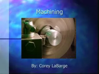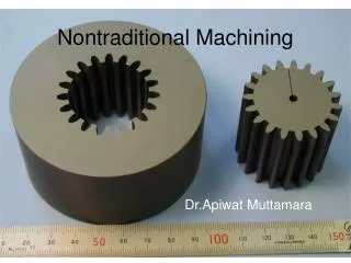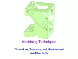
Machining
Machining. Q7. Introduction. Topics Machines Drill Lathe Grinder Milling machine Shaping machine CNC machines. Robotics. Introduction. Associated Terms. Cutting fluids. Surface finish Forces Measurement's. Tool geometry. Work holding. Chip formation. 1. PARTS OF DRILL BIT.


Machining
E N D
Presentation Transcript
Machining Q7
Introduction. Topics Machines • Drill • Lathe • Grinder • Milling machine • Shaping machine • CNC machines. • Robotics
Introduction. Associated Terms. • Cutting fluids. • Surface finish • Forces • Measurement's. • Tool geometry. • Work holding. • Chip formation
1. PARTS OF DRILL BIT • A: Body. This section of the drill contains the drill flutes. • B: Parallel shanks. This section of the drill bit is held by the chuck. • C: Flank: This determines the cutting lip length • D: Flute. These provide the passageway for swarf to escape up the drill • E:. Land. This is the thickness of the cutting lip • F: Web: this is the edge between both flanks
Reaming. • Reamers are used to accurately finish holes drilled by drill bits. • Reamers contain more flutes than a drill. Drill bitReamer
Terms. Countersinking is the enlarging of the mouth of a drilled hole to accommodate countersunk head screws and rivets.
Pilot Hole A pilot hole is drilled prior to drilling a large hole.
Counterboring It is the increasing of the hole diameter to a certain depth to accommodate cheese head screws
Lathe Processes. • Parallel turning. • Facing off.
Lathe Processes Cont. • Taper turning • Parting off/Undercut
Lathe Processes Cont • Radius nose turning. • Drilling.
Cutting Tools. • The tool used in a lathe is known as a single point cutting tool. It has one cutting edge or point whereas a drill has two cutting edges and a file has numerous points or teeth.
Lathe Tool Shears Workpiece. • The lathe tool shear the metal rather than cuts. It can only do so if there is relative motion between the tool and the work piece. • For example the work is rotation and the tool is moved into its path such that it forms an obstruction and shearing takes place.
Screw Cutting. It is slightly more difficult task than plain turning. It involves more accurate setting up of the tool and exact setting of feed in relation to the work rotation. Once this is done however, the process is easy.
Grinder • A bench grinder or pedestal grinder is a machine used to drive an abrasive wheel (or wheels).
Grinding Wheels. • The wheel can be fitted to the spindle of the grinding machine. • The wheel rotates at high speed and the work is brought into contact with it.
Parts of the Grinding Wheel. • There are two main constituents in a grinding wheel: • 1 The abrasive (this is the grit) • 2. The bond. (this holds the abrasive in a rigid shape.
The Abrasive. • The abrasive forms the cutting edges. • Usually, a particular abrasive type is selected to suit the materials being ground. • The surface finish required on the work influences the size of the abrasive grains chosen.
The Bond • The bond, while designed to hold the abrasive in the form of a wheel, also must release the grains when they become worn. • There will be greater pressure on grain from the work if it has lost its cutting ability so it well become dislodged exposing sharper grains underneath.
Dressing the Grinding Wheel. • In the grinding process, wheel dressing is used to restore the cutting surface of any irregularities. Grinding wheels are designed to have a selfdressing action in which grains should break free and expose sharp edges. • Wheel dressing will renew a sharp cutting face and correct irregularities such as wheel concentricity. • The process can remove any undulations from the wheel.
Loading Grinding Wheel • Loading of a grinding wheel occurs when small particles of the metal being machined clog up the spaces between the abrasive grains in the grinding wheel
Glazed Grinding Wheel. • Glazing occurs when abrasive particles which have lost their edge remain trapped in the grinding wheel.
DIAMOND STICK WHEEL DRESSER http://its.fvtc.edu/machshop1/Bench/grinder/video/dresssideLG.mov
The Wheel Grit • Coarse Grit Fine Grit
Surface Grinding • A metal cutting process in which flat and extremely smooth surfaces are produced. The grinding wheel rotates and the workpiece, usually held in a magnetic chuck, is fed to and fro continuously. • At the end of each stroke, the table is moved across the wheel by a small amount. • The grinding wheel can be lowered to take a new cut
Work holding for the Surface Grinding. • The magnetic chuck is used to hold work on the surface grinder. It consists of a top plate, which contains magnetic inserts, a casing which contains permanent magnets. • To turn the chuck on the magnets are moved on line with the inserts, which creates a magnetic force through the work piece. • The force is strong enough to hold the work piece securely in position.
Other Workholding methods for Surface Grinding. • Adaptor plates, sine chuck, chuck plates, universal plates and magnetic chucks
Cylindrical Grinding • This is used to produce cylindrical objects. The workpiece is held in a chuck, or between centres, and set to rotate. • Then a grinding wheel, when brought into contact with the workpiece, will produce a smooth accurate cylinder. • Long workpieces can be ground as the table can reciprocate and the wheel head can move towards the workpiece. • Tapered work can also be carried out.
Machining processes used to produce cylindrical surfaces include: • Parallel turning, Cylindrical grinding, Drilling, Reaming, Boring, Milling.
Safety features on a Pedestal Grinder: • A face guard is supplied with the machine to protect against grinding debris. • Easily accessible switches allow the machine to be turned off quickly. • Modern machines are designed to stop quickly. • The machine should be firmly attached to the ground.
Milling - Industrial Applications • Milling machines are widely used in the tool and die making industry and are commonly used in the manufacturing industry for the production of a wide range of components. • Typical examples are the milling of flat surfaces, indexing, gear cutting, as well as the cutting of slots and key ways.
Milling Processes. • Milling is a metal removal process by means of using a rotating cutter having one or more cutting teeth.
Milling Processes Cont. • Cutting action is carried out by feeding the workpiece against the rotating cutter. • Thus the spindle speed the table feed the depth of cut and rotation direction of the cutter become the main parameters of the process.
Milling • Milling is the machining of a surface using a cutter which has a number of teeth. A flat surface may be produced or special cutters can be used to form profiled surfaces. • The most common type of milling machine is the knee and column type. • The spindle is fixed in the column or main body and the table is mounted on a knee.
Main Parts • Base: cast iron base houses the cutting-fluid reservoir and has a rigid construction to prevent vibration. • Column: mounted on the base, the column contains the spindle. • Knee: allows for vertical movement of the table. • Saddle: provides transverse movement of the table. • Table: work pieces and work holding equipment are located and clamped. • Spindle: provides the drive for the milling cutters
Types of Milling Machines. • Most of the milling machine are constructed of a column and knee type structure and they are classified into two main types namely Horizontal milling machine and Vertical milling machine.
Horizontal Type Milling cutters are mounted on the arbour.
The main spindle is mounted horizontally near the top of the column. • The machine capacity is determined by the maximum distance from the table to the spindle as well as working surface size and travel in all directions. • The milling cutters have a hole in them in order to be mounted on an arbour. • The cutters are usually large in diameter and are found in a range of types including slab, side and face, saw, angle and form cutters
Vertical Type Variety of cutters can be used
The spindle is mounted vertically in a head at the top of the column. • The milling cutters are generally mounted in a chuck. • There are a range of end mills, slot drills and profiled cutters (angle, ball-nose, dovetail, tee-slot, corner-rounding, etc.)