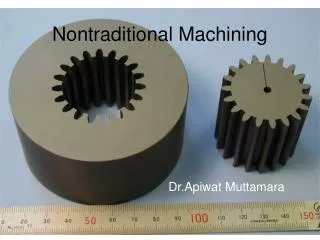
Conventional Machining
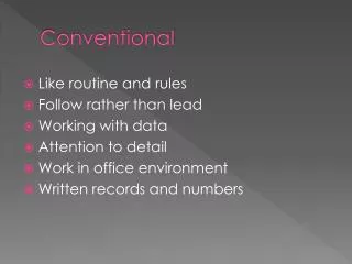
Conventional Machining. Md. Yeasin Bhuiyan Lecturer Department of Mechanical Engineering BUET. Manufacturing Engineering. Rotational. Non-rotational. Introduction.

Conventional Machining
E N D
Presentation Transcript
Conventional Machining Md. YeasinBhuiyan Lecturer Department of Mechanical Engineering BUET
Rotational Non-rotational Introduction • Machined parts can be classified as rotational or non-rotational. A rotationalworkpart has a cylindrical or disk-like shape. The characteristics operation that produces this geometry is one in which a cutting tool removes material from rotating workpart. Examples include turning and boring. Drilling is closely related except that an internal cylindrical shape is created and the tool rotates in most drilling operations. • A non-rotational (also called prismatic) workpart is block-like or plate like. This geometry is achieved by linear motions of the workpart, combined with either rotating or linear tool motion. Operations in this category include milling, shaping, planning and sawing
Introduction • In generating, the geometry of the workpart is determined by the feed trajectory of the cutting tool. Examples of generating the work shape in machining include straight turning, taper turning, contour turning, peripheral milling and profile milling. • In forming, the shape of the part is created by the geometry of the cutting tool. In effect, the cutting edge of the tool has the reverse of the shape to be performed on the part surface. Form turning, drilling, and broaching are examples of the case. • Forming and generating are sometimes combined in one operation, such as in thread cutting on a lathe and slot milling.
(a) Straight turning (c) Contour turning (b) Taper turning (d) Plain milling (e) Profile turning Generating Shape in Machining
(a) (c) (b) Forming Shape in Machining Forming to create shape in machining (a) form turning (b) broaching and (b) drilling
(a) Combination of forming and generating to create shape (a) slot milling and (b) thread cutting (b) Forming & Generating Shape
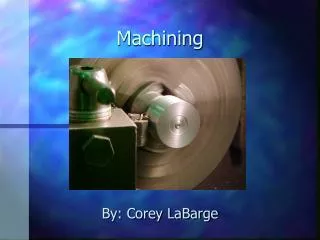
Turning • Turning is the process whereby a centre lathe is used to produce "solids of revolution". It can be done manually, in a traditional form of lathe, which frequently requires continuous supervision by the operator, or by using a computer controlled and automated lathe which does not. • This type of machine tool is referred to as having computer numerical control, better known as CNC and is commonly used with many other types of machine tool besides the lathe.
Facing Contour turning Form turning Basic Turning Operations • Facing: The tool is fed radially into the rotating work on one end to create a flat surface on the end. Contour turning: Instead of feeding the tool along a straight line parallel to the axis of rotation as in turning, the tool follows a contour that is other than straight, thus creating a contoured form in the turned part. Form turning: In this operation, sometimes called forming, the tool has a shape that is imparted to the work by plunging the tool radially into the work.
Taper turning Cutoff Chamfering Basic Turning Operations • Taper turning: Instead of feed the tool parallel to the axis of rotation of the work, the tool is fed at an angle, thus creating a taper cylinder or conical shape. Chamfering: The cutting edge of the tool is used to cut an angle on the corner of the cylinder, forming what is called a “chamfer”. Cutoff: The tool is fed radially into the rotating work at some location along its length to cut off the end of the part. This operation is sometimes referred to as parting.
Knurling Boring Threading Drilling Basic Turning Operations • Boring: A single point is fed linearly. parallel to the axis of rotation, on the inside diameter of an existing hole in the part. Threading: A pointed tool is fed linearly across the outside surface of the rotating workpart in a direction parallel to the axis of rotation at a large effective feed rate, thus creating threads in the cylinder. Drilling: Drilling can be performed on a lathe by feeding the drill into the rotating work along its axis. Reaming can be performed in a similar way. Knurling: This is not a machining operation because it does not involve cutting of material. Instead, it is a metal forming operation used to produce a regular cross hatched pattern in the work surface.
Boring & Reaming • Boring consists of producing circular internal profiles in hollow workpieces or on a hole made by drilling or another process and is carried out using cutting tools that are similar to those used in turning. • Reams remove small amounts of material to ensure exact hole size and improve hole surface finish • Reams are either hand operated or machined at slow speed
Vertical Boring Mill Figure: Schematic illustration of the components of a vertical boring mill
Manufacturing Engineering Lab Practice
Types of Lathe • Speed Lathes • Limited to headstock, tailstock, and simple tool post. • Limited to 3-4 speeds • High spindle speeds, • For light work such a wood turning, metal polishing, or metal spinning • Engine Lathes • Most common type • Variable in design from low to high power designs • Broad range of lengths up to 60ft long • Tool room Lathes • Specialized Engine lathe with greater accuracy. • Broader range of speeds and feeds • Greater versatility for tool and die manufacturing • Turret Lathes • Turret on tool post rotates to position a variety of tools • Capstan wheel used to pull to away from work piece to position next tool • A number of tools set up on machine, each brought up in quick succession to complete the part in a single setup
Lathe Design and Terminology • Bed • Gray cast for vibration dampening • Headstock assembly • Spindle • Transmission • Drive motor • Tailstock assembly • Longitudinal way clamp • Transverse way clamp • Quill for cutting tools, live centers, or dead centers • Quick-change gearbox • Powers Carriage Assembly movement with lead screw • Carriage Assembly • Fixed to cross slide • Holds tool post at variable orientations • Provides longitudinal and transverse movement of tooling • Ways • Provides precise guidance to carriage assembly and tailstock
Computer Numerical Controls (CNC) Lathe • In the most advanced lathes, movement and control of the machine and its components are actuated by computer numerical controls (CNC); the features of such a lathe are shown in the following Figure.
Different Parts of CNC Lathe • Vice: This holds the material to be cut or shaped when the CNC begins to machine. Normally the vice will be like a clamp that holds the material in the correct position. • Guard: The guard protects the person using the CNC. When the CNC is machining the material small pieces can be 'shoot' off the material at high speed. This could be dangerous if a piece hit the person operating the machine. The guard completely encloses the dangerous areas of the CNC.
Different Parts of CNC Lathe • Chuck: This holds the material that is to be shaped. The material must be placed in it very carefully so that when the CNC is working the material is not thrown out at high speed. • Motor: The motor is enclosed inside the machine. This is the part that rotates the chuck at high speed. • Lathe Bed: The base of the machine. Usually a CNC is bolted down so that it cannot move through the vibration of the machine when it is working. • Cutting Tool: This is usually made from high quality steel and it is the part that actually cuts the material to be shaped.
Cutting Tools for Lathes • Tools consists of cutting surface and support Figure: Common types of forged tool holders: (a) right-hand turning, (b) facing, (c) grooving cutoff, (d) boring, (e) threading.
Several types of lathe collets Lathe Collets