Simulation Techniques
Simulation Techniques. Computer Simulation and Modelling.

Simulation Techniques
E N D
Presentation Transcript
Computer Simulation and Modelling Computer simulation modeling is a discipline gaining popularity in both government and industry. Computer simulation modeling can assist in the design, creation, and evaluation of complex systems. Designers, program managers, analysts, and engineers use computer simulation modeling to understand and evaluate ‘what if’ case scenarios. It can model a real or proposed system using computer software and is useful when changes to the actual system are difficult to implement, involve high costs, or are impractical. Some examples of computer simulation modeling familiar to most of us include: weather forecasting, flight simulators used for training pilots, and car crash modeling.
Benefits: • Gain greater understanding of a process. • Identifyproblem areas or bottlenecks in processes. • Evaluate effect of systems or process changes such as demand, resources, supply, and constraints, • Identify actions needed upstream or downstream relative to a given operation, organization, or activity to either improve or mitigate processes or events • Evaluate impact of changes in policy prior to implementation
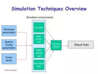
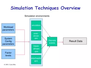
Types of Simulation Models: • Discrete Models • Changes to the system occur at specific times • Division of Property Management trouble calls • Acquisition or construction business processes • A manufacturing system with parts entering and leaving at specific times • Continuous Models • The state of the system changes continuously over time • A reservoir as water flows in and out • Chilled water or steam distribution • Mixed Models • Contains both discrete and continuous elements • A refinery with continuously changing pressure inside vessels and discreetly occurring shutdowns • Chilled water distribution including plant shutdowns
Giriş • OR (OperationalResearch yaklaşımı) • 1. Problem formulation • 2. Construction of the model • 3. Model validation • 4. Using the model, evaluate various available alternatives (solution) • 5. Implementation and maintenance of the solution
Model? • A model is a representation of thestructure of a real-life system. In general, models can be classified as follows: iconic, analogue, and symbolic. • İconic: Sistemin küçük bir hali • Analojik: bir çok sistemin karşılığı olarak kütle, damper, yay, vb. • Sembolik: Matematik denklemi veya bilgisayar programı
Sembolik Modeller • Deterministik: Olasılık içermeyen • Lineer Prog. NonLinearProg. DinamicProg. • Stochastic*: • QueueingTheory, StochasticProcessler, reliability, andsimulationtechniques. • *In probability theory, a stochastic system is one whose state is non-deterministic. The subsequent state of a stochastic system is determined both by the system's predictable actions and by a random element. (Stochastic-Wikipedia)
SimulationTechniques • Randomness • Ne zaman kullanmalıyım: • «Diğer tüm metotlar işe yaramazsa, Simulasyon kullan»
When building a simulation model of a real-life system under investigation, one does not simulate the whole system. Rather, one simulates those sub-systems which are related to the problems at hand.
Why Do We Simulte ? • For Example • one is interested in quantifying the performance of a system under study for various values of its input parameters. • Such quantified measures of performance can be very useful in the managerial decision process.
Controllable UnControllable • All the relevant variables of a system under study are organized into two groups. • as given and are not to be manipulated (uncontrollable variable) • and those which are to be manipulated • whether they are affected or not during a simulation run • not affected is called exogenous. • affected is called endogenous.
Example • For Single Server Queue • Exogenous variables • The time interval between two successive arrivals. • The service time of a customer. • Number of servers. • Priority discipline. • Endogenous variables • Mean waiting time in the queue. • Mean number of customers in the queue. For instance, if we wish to find the impact of the number of servers on the mean waiting time in the queue, then the number of servers becomes an controllable variable. The remaining variables-the time interval between two arrivals and the service time, will remain fixed. (uncontrollable variables)
STATUS VARIABLE • These variables form the backbone of any simulation model. At any instance, during a simulation run, one should be able to determine how things stand in the system using these variables
Basic simulation methodology: Examples • The machine interference problem • Let us consider a single server queue with a finite population known as the machine interference problem. Need: Modelling of machines, Computer Modelling • Scenario • Each machine is operational for a period of time and then it breaks down. • assume that there is one repairman • A machine remains broken down until it is fixed by the repairman.
Scenario (Cont.) • Broken down machines are served in a FIFO manner, the service is non preemptive. • Question • the total down time of a machine ? • made up of the time it has to "queue" for the repairman and the time it takes for the repairman to fix it • A machine becomes immediately operational after it has been fixed
What Do we Know • In general, • one has information regarding the operational time and the repair time of a machine • However, in order to determine the down time of a machine, one should be able to calculate the queueing time for the repairman • If this quantity is known, then one can calculate the utilization of a machine. • Other quantities of interest could be the utilization of the repairman.
Calculations • For simplicity, we will assume that the operational time of each machine is equal to 10 units of time. • Also, the repair time of each machine is equal to 5 units of time. • we assume that all the machines have identical constant operational times and Repair times.
Events to Change the STATUS of the system • The first and most important step in building a simulation model of the above system, is to identify the basic events whose occurrence will alter the status of the system. • This brings up the problem of having to define the status variables of the above problem. • The selection of the status variables depends mainly upon the type of performance measures we want to obtain about the system under study.
N • In this problem, the most important status variable is n, • What is N?? • the number of broken down machines, i.e., those waiting in the queue plus the one being repaired • If n=0, the queue is empty and the repairman is idle. • If n=1, then the queue is empty and the repairman is busy. • If n>1, then the repairman is busy and there are n-1 broken down machines in the queue.
Events that Change the N • A machine breaks down, i.e., an arrival occurs at the queue. • A machine is fixed, i.e., a departure occurs from the queue.
Needed Set of Variables Clocks • Clocks will keep track of the time instants at which an arrival or departure event will occur. • We need to associate a clock for each machine that will show the next break down time/ will arrive the repairman’s queue • Only the clock of the operational machine are in interest • another clock which shows the time instant at which a machine currently being repaired will become operational • it will cause a departure event to occur. • In total, if we have m machines, we need m+1 clocks. Each of these clocks is associated with the occurrence of an event. • m clocks are associated with m arrival events and one clock is associated with the departure event. • MASTER CLOCK simply keeps track of the simulated time. • The heart of the simulation model centers around the manipulation of these events. • the model decides which of all the possible events will occur next. • Then the master clock is advanced to this time instant, and the model takes action as indicated in the flow-charts given in figures 1.5 and 1.6. This event manipulation approach is depicted in figure 1.7
Hand Simulations • assume that we have 3 machines. • Let CL1, CL2, and CL3 be the clocks associated with machine 1, 2, and 3 respectively (arrival event clocks). • Let CL4 be the clock associated with the departure event. • Let MC be the master clock • Let R indicate whether the repairman is busy or idle • We assume that at time zero all three machines are operational and that CL1=1, CL2=4, CL3=9. • These are known as initial conditions. • We note that in order to schedule a new arrival time we simply have to set the associated clock to MC+10 • Similarly, each time a new repair service begins we set CL4=MC+5
A token-based access scheme • We consider a computer network consisting of a number of nodes interconnected via a shared wired or wireless transport medium, • Access to the shared medium is controlled by a token. a node cannot transmit on the network unless it has the token. • There is a single token that visits the nodes in a certain logical sequence
A token-based access scheme (cont.) • Nodes are logically connected so that they form a logical ring • The order is not necessarily be the same w-the order they have attached to the network • We will assume that the token never gets lost. • A node cannot transmit unless it has the token • When a node receives the token, from its previous logical upstream node, it may keep it for a period of time up to T • During this time, the node transmits packets. • PacketData + HeadersSource/Destination Address +Control Fields • The node surrenders the token when: • time T has run out • it has transmitted out all the packets in its queue before T expires • it receives the token at a time when it has no packets in its queue to transmit. • if time T runs out and the node is in the process of transmitting a packet, it will complete the transmission and then it will surrender the token. • Surrendering the token means, that the node will transmit it to its next downstream logical neighbor.
Token based *Cont. • Conceptually, this network can be seen as comprising of a number of queues, one per node. Only the queue that has the token can transmit packets. • The token can be seen as a server
Events • Switch-over Time :The time it takes for the token to switch from one queue to the next • Polling Systems • For each queue, there is an arrival event and service completion event. • For the token, there is a time of arrival at the next queue event and the time when the token has to be surrendered to the next node, known as the time-out. • For each queue, we keep track of the time of arrival of the next packet, the number of customers in the queue, and the time a packet is scheduled to depart, if it is being transmitted. • For the token, we keep track of the time of arrival at the next queue, the number of the queue that may hold the token, and the time-out.
Hand Simulation • 3nodes, 3 queues • Inter arrival times to queue 1, 2, 3, is constant 10, 15, 20 UT respectively • T =15 UT • The time it take s to transmit a packet is 6 UT • The Switch-Over time is 1 • Initial Condition: we assume that the system is empty at time zero, and the first arrival to queues 1, 2, and 3 will occur at time 2, 4 and 6 respectively. • at time zero, the token is in queue 1. • In case when an arrival and a departure occur simultaneously at the same queue, we will assume that the arrival occurs first. • In addition, if the token and a packet arrive at a queue at the same time, we will assume that the packet arrives first.
Variable List • MC: Master clock • ATi: Arrival time clock at queue i, i=1,2,3 • DTi: Departure time clock from queue i, i=1,2,3 • TOUT: Time out clock for token • ANH: Arrival time clock of token to next queue
Two Stage Manufacturing system • Let us consider a two stage manufacturing system • Queue 1 • infinitecapacityqueue • Queue 2 • Finitecapacity
When queue 2 becomes full, server 1 stops. More specifically, upon service completion at server 1, the server gets blocked if the queue 2 is full • Server 1 will remain blocked until a customer departs from queue 2. In this case, a space will become available in queue 2 and the served customer in front of server 1 will be able to move into queue 2, thus freeing the server to serve other customer in queue 1. • Each server may also break down. • we will assume that a server may break down whether it is busy or idle • not provide service until it is repaired. • If a customer was in service when the breakdown occurred, the customer will resume its service after the server is repaired without any loss to the service it received up to the time of the breakdown
Events (and associated clocks) may occur: • Arrival of a customer to queue 1 (clock AT) • Service completion at server 1 (clock DT1) • Service completion at server 2 (clock DT2) • Server 1 breaks down (clock BR1) • Server 1 becomes operational (clock OP1) • Server 2 breaks down (clock BR2) • Server 2 becomes operational (clock OP2)
Arrival to queue 1. • Arrival to queue 1 (new value for AT clock): This event is always scheduled each time an arrival occurs. • Service completion at server 1 (new value for DT1 clock): This event will be triggered if the new arrival finds the server idle.
Service completion at server 1: • Service completion at server 1(new value for DT1 clock): This event will occur if there is one or more customers in queue 1. • Service completion at server 2 (new value for DT2 clock): This event will occur if the customer who just completed its service at server 1 finds server 2 idle. • The occurrence of a service completion event at server 1 may cause server 1 to get blocked, if queue 2 is full.
Service completion at server 2: • Service completion at server 2 (new value for D21 clock): This event will occur if there is one or more customers in queue 2. • Service completion at server 1 (new value for DT1 clock): This event will occur if server 1 was blocked.
Server 1 breaks down: • Server 1 becomes operational (new value for OP1 clock): This event gives the time in the future when the server will be repaired and will become operational. If the server was busy when it broke down, update the clock of the service completion event at server 1 to reflect the delay due to the repair.
Server 1 becomes operational: • Server 1 breaks down (new value for BR1 clock): This event gives the time in the future when the server will break down. During this time the server is operational. • Service completion time (new value for DT1): If the server was idle when it broke down, and queue 1 is not empty at the moment it becomes operational, then a new service will begin.
Server 2 breaks down: • Server 2 becomes operational (new value for OP2 clock): This event gives the time in the future when server 2 will be repaired, and therefore it will become operational. During that time the server is broken down. • If server 2 was busy when it broke down, update the clock of the service completion event at server 2 to reflect the delay due to the repair.
Server 2 becomes operational: • Server 2 breaks down (new value for BR2 clock): This event gives the time in the future when server 2 will break down. During this time the server is operational. • Service completion time (new value for DT2): If the server was idle when it broke down, and queue 2 is not empty at the moment it becomes operational, then a new service will begin.