Integrated Circuit Design in CISC101
260 likes | 330 Vues
Explore the basics of integrated circuits with examples of logical gates and circuit design for adding binary numbers in CISC101 under Prof. McLeod's guidance.

Integrated Circuit Design in CISC101
E N D
Presentation Transcript
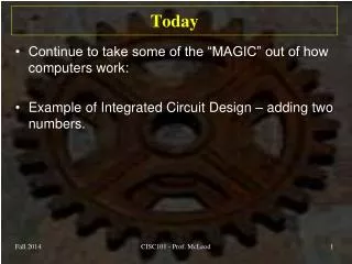
Today • Continue to take some of the “MAGIC” out of how computers work: • Example of Integrated Circuit Design – adding two numbers. CISC101 - Prof. McLeod
Summary: “Truth” or Logic Tables AND OR I1 I2 Output I1 I2 Output NOT I Output 0 0 0 0 0 0 0 1 0 0 1 1 0 1 1 0 0 1 0 1 1 0 1 1 1 1 1 1 NAND NOR XOR I1 I2 Output I1 I2 Output I1 I2 Output 0 0 1 0 0 1 0 0 0 0 1 1 0 1 0 0 1 1 1 0 1 1 0 0 1 0 1 1 1 0 1 1 0 1 1 0 CISC101 - Prof. McLeod
Summary, Cont. • Gates: You can use transistors to build a circuit, or “gate”, that provides the logic for each of these operators. • Notation: • ab (you will also see just “ab”) means “a AND b” • a+b means “ a OR b” • a means NOT(a) • ab means “a XOR b” CISC101 - Prof. McLeod
Digital Circuits • Generally, a digital circuit can be represented by: • Remember that an input or output can only be either on (1) or off (0). • The gates defined above can be used to design circuits that provide a desired logic. CISC101 - Prof. McLeod
For Example: Adding Binary Numbers • Show how to build a circuit to add binary numbers - a “one bit full adder”. • First: How do youadd decimal (base 10) numbers?: 0 1 0 0 0 4 5 7 0 1 2 3 4 7 2 6 9 1 7 3 Carry digits + Sum CISC101 - Prof. McLeod
Adding Binary Numbers, for Example • The binary numeric system consists of zeros and ones – only. Also called “base 2”. • Adding binary numbers: Carry bits 1 1 1 0 0 0 1 1 0 1 0 1 1 0 0 1 1 0 1 1 0 1 0 0 1 1 0 0 0 1 1 1 0 0 + Sum CISC101 - Prof. McLeod
Half Bit Adder • Look at the first column of the process: carry output 1 1 1 0 0 0 1 1 0 1 0 1 1 0 0 1 1 0 1 1 0 1 0 0 1 1 0 0 0 1 1 1 0 0 input 1 + input 2 sum output CISC101 - Prof. McLeod
Half Bit Adder - Cont. • Construct a truth table to describe the operation, considering every possible input: Which gate produces the sum? The carry? CISC101 - Prof. McLeod
Half Bit Adder - Cont. • Write the boolean expressions for the sum output and the carry output: • Where “S” is the sum output and “Co” is the carry output. or CISC101 - Prof. McLeod
Half Bit Adder - Cont. • Logical diagram for the sum output: • (This is another way to build a “XOR” gate.) not and or CISC101 - Prof. McLeod
Test XOR Gate Logic not and 1 0 or 0 0 1 1 1 0 1 0 1 1 1 1 0 0 1 0 CISC101 - Prof. McLeod
Test XOR Gate, Cont. not and 0 1 or 0 0 0 0 0 0 1 1 0 0 1 0 1 0 1 0 CISC101 - Prof. McLeod
Half Bit Adder - Cont. • Back to the expression for “S”: So, S can be generated by an “XOR” gate and Co by an “AND” gate: I1 S I2 Co CISC101 - Prof. McLeod
Full Bit Adder • Look at one column of the addition process that also adds the carry bit: carry output carry input 1 1 1 0 0 0 1 1 0 1 0 1 1 0 0 1 1 0 1 1 0 1 0 0 1 1 0 0 0 1 1 1 0 0 input 1 + input 2 sum output CISC101 - Prof. McLeod
Full Bit Adder - Cont. • Construct a logic table to describe what happens - list every input possibility: CISC101 - Prof. McLeod
Full Bit Adder - Cont. • Create boolean expressions: • Where “I” is input, “Ci” is carry input, “Co” is carry output and “S” is sum output. • (Don’t panic! You don’t have to know where these expressions come from and you don’t have to remember them!) CISC101 - Prof. McLeod
Full Bit Adder - Cont. • You can write the logical diagram from these expressions as they are but it can be simplified using two “half-bit” adders and an OR gate: Ci S I1 Co I2 CISC101 - Prof. McLeod
Full Bit Adder - Cont. • How many transistors required? • AND and OR have 2 each, NOT has 1 (and a resistor) • Then XOR must have 8 (2 NOTs, 2 ANDs, 1 OR) • Half-bit adder must have 10 (1 XOR, 1 AND) • Full-bit adder must have 22 (2 half-bits, 1 OR) CISC101 - Prof. McLeod
N Bit Full Adder CISC101 - Prof. McLeod
N Bit Full Adder – Cont. • How many transistors? • 22 times N • Integers might occupy 4 bytes or 32 bits for example: 704 transistors, minimum! • Just to add two integers! CISC101 - Prof. McLeod
Aside - Minecraft Constructions • People with a lot of time on their hands have built adders like these in Minecraft. • For example, see these Youtube videos: • One bit: http://www.youtube.com/watch?v=tTAuD3Y4meQ • 32 bit: http://www.youtube.com/watch?v=R-UdWu60eaI CISC101 - Prof. McLeod
Other Operations • So, a full adder can be used to produce a N+1-bit number as the sum of two other N bit numbers. • How about multiplication? • From Grade 4: 11011 1101 11011 000000 1101100 11011000 101011111 Base 2: 27 • 13 81 270 351 Base 10: CISC101 - Prof. McLeod
Multiplication, Cont. • So what kind of logic would you build to do multiplication of x times y? • Create a running sum, s. • For each digit, xi: • If xi equals 1 then add 2i y to x. • Use a bitwise shift operation to calculate 2i y (ie. Add a zero to the right of the number). • So, an N-bit adder would be used along with some other simple circuits. CISC101 - Prof. McLeod
Summary of Digital Logic • The CPU needs to carry out many other operations than just addition: • subtraction • comparison • multiplication • division, etc. • Some common functions (trig, exp, log, etc) would work faster if they were hard coded into the processor too. • Lots (and lots!) of transistors!! CISC101 - Prof. McLeod
Aside – My CPU, for Example • Intel Core i7 2670QM, 2.2 GHz (up to 3.2 GHz): • 32 nm technology • 6MB cache • 4 cores, 8 threads • 995 million transistors, total. • 988 pins. CISC101 - Prof. McLeod
“Don’t Worry, Be Happy!” • You do not need to be able to design microprocessor circuits! • Besides, INTEL and AMD have some fancy programs that do all the work. • The purpose of this discussion has been to give you some idea of how an integrated circuit carries out instructions. (Not MAGIC! Just some good technology!) CISC101 - Prof. McLeod