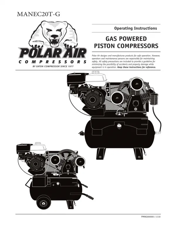
Gas Powered Piston Compressors - Operating Instructions
120 likes | 258 Vues
Polar Air designs and manufactures products for safe operation. However, operators and maintenance persons are responsible for maintaining safety. All safety precautions are included to provide a guideline for minimizing the possibility of accidents and property damage while equipment is in operation. To know about gas driven piston compressor, visit - https://www.eatoncompressor.com/piston-gas-powered

Gas Powered Piston Compressors - Operating Instructions
E N D
Presentation Transcript
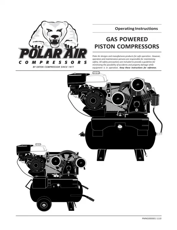
Operating Instructions GAS POWERED PISTON COMPRESSORS Polar Air designs and manufactures products for safe operation. However, operators and maintenance persons are responsible for maintaining safety. All safety precautions are included to provide a guideline for minimizing the possibility of accidents and property damage while equipment is in operation. Keep these instructions for reference. PMNG000001 1110
PolarAirGasPowered,PistonCompressors Contents Page No. Page No. Operation ............................................................... 6 Model Specification Chart .................................... 2 Safety Rules ..................................................... 6 Description ............................................................ 3 Start Up ............................................................... 7 Safety Information ................................................ 3 Maintenance .......................................................... 8 Tag Definitions ................................................ 3 Safety Steps ..................................................... 8 Basic Guidelines .............................................. 3 Belt Adjustment ............................................... 8 Breathable Air ................................................. 4 Changing Oil ..................................................... 8 Pressurized Components .................................... 4 Safety Valve ..................................................... 9 Personal Protective Equipment .......................... 4 Tank ............................................................................ 9 Inspection .............................................................. 4 Maintenance Schedule .......................................... 9 Forklift Safety .................................................. 4 Troubleshooting ............................................. 10-11 Lifting Safety ................................................... 4 Warranty ................................................................ 12 Installation ......................................................... 5 Area ..................................................................... 5 Piping Safety Steps ......................................... 5 Piping / Tank Installation ............................. 5 Truck Installation ............................................. 6 Battery Component ............................................ 6 Polar Air Gas Powered, Piston Air Compressors Model PGPS0817WL PGES0817WL PGES1330ST PGES1830ST PGES1860ST PGES2480ST Description 8 HP HONDA PORTABLE 8 HP HONDA 13 HP, 30 GAL. HONDA 18 HP, 30 GAL. HONDA 18 HP, 60 GAL. HONDA 24 HP, 80 GAL. HONDA SCFM 18 @ 150 18 @ 150 24 @ 175 34 @ 175 34 @ 175 52 @ 175 Motor Power 8HP 8HP 13HP 18HP 18HP 24HP Motor RPM 3200 3200 3200 3200 3200 3200 Tank Size 17 17 30 30 60 80 Pump Model APP2V0732S APP2V0732S APP3Y0732T APP4V1043T APP4V1043T APP3Y2062T Pump RPM 650 650 820 800 800 640 Outlet Size Dimensions L•W•H 3/4” 3/4” 3/4” 3/4” 3/4” 1” 46”x 21”x37” 46”x 21”x37” 51”x 23”x40” 44”x 23”x44” 51” x 23”x50” 72”x 25”x50” (inches) Weight (lbs.) 275 275 395 540 610 870 Shipping Weight 310 310 326 628 703 970 Electric Start No Yes Yes Yes Yes Yes 2
OperatingInstructions Description Unit configuration and appearance varies by model. Callouts are for general identification. Intercooler Air filter Gas tank Electric start Head unloader valve Engine start pull cord Raised motor mounting plate Check valve Air receiver / Tank Oil site glass Tank drain valve Ball valve (Air outlet) Pressure gauge Tank anchor bolt location (4, typ.) Safety Basic Guidelines 1.Allow only trained, authorized persons who have read and understood these operating instructions to use this compressor. Failure to follow the instructions, procedures and safety precautions in this manual can result in accidents and injuries. 2.NEVER start or operate the compressor under unsafe conditions. Tag the compressor, disconnect and lock out all power to it to prevent accidental start-up until the condi- tion is corrected. 3.Install, use and operate the compressor only in full compliance with all pertinent OSHA regulations and all applicable Federal, State & Local Codes, standards and regulations. 4.NEVER modify the compressor and/or controls in any way. 5.Keep a first aid kit in a convenient place. Seek medical assistance promptly in case of injury. Avoid infection by caring for any small cuts and burns promptly. This manual contains very important information to know and understand. This is provided for SAFETY and to PREVENT EQUIPMENT PROBLEMS. To help un- derstand this information, observe the following: Danger indicates an imminently hazardous situation which, if not avoided, will result in death or serious injury. Warning indicates a potentially hazardous situation which, if not avoided, could result in death or serious injury. Caution indicates a potentially hazardous situation which, if not avoided, may result in minor or moderate injury. Notice indicates important infor- mation, that if not followed, may cause damage to equipment. Readallmanualsincludedwiththis productcarefully.Bethoroughly familiarwiththe controlsandthe proper useofthe equipment. MANUAL 3
PolarAirGasPowered,PistonCompressors Forklift Safety 1.Make sure lift operator stays aware while moving compressor. 2.Be sure load is secure and well balanced before moving the compressor. 3.Make sure forks are fully engaged and level before lifting or moving compressor. 4.Keep load as low as possible and observe safe operating practices. Breathable Air 1.NEVER use air from this compressor for breathable air except in full compliance with OSHA Standards 29 CFR 1910 and any other Federal, State or Local codes or regulations. Death or serious injury can result from inhaling compressed air without using proper safety equipment. See OSHA standards on safety equipment. Keep unit level and be careful of top heavy load 2.DO NOT use air line anti-icer systems in air lines supplying respirators or other equip- ment used to produce breathable air. DO NOT discharge air from these systems in unventi- lated or other confined areas. Pressurized Components This equipment is supplied with a ASME designed pressure vessel protected by an ASME rated relief valve. Pull the ring before each use to make sure the valve is functional. Refer to figure NOT attempt to open valve while the machine is under pressure. . DO Figure 1: Keep unit level Personal Protective Equipment Be sure all operators and others around the compressor and its controls comply with all appli- cable OSHA, Federal, State and Local regulations, codes and standards relating to personal protec- tive equipment. This includes respiratory protec- tive equipment, protection for the extremities, protective clothing, protective shields and barri- ers, electrical protective equipment, and personal hearing protective equipment. Lifting Safety 1.Carefully inspect all lifting equipment and make sure it is in good condition. Rated capacity should exceed compressor weight. Make sure lifting hook has a functional safety latch or equivalent and is properly attached to lifting feature. 2.Make sure lifting points are in good condition and tighten any loose nuts or bolts before lifting. 3.Use provided lifting feature or appropriate sling. A sling must be used when moving compressor with a helicopter or other air-borne equipment. Be sure to follow OSHA standards 29 CFR 1910 Subpart N. 4.Use guide ropes or equivalent to prevent twisting or swinging of the compressor while it is in the air and NEVER attempt to lift in high winds. Keep compressor as low to the ground as possible. 5.Keep persons away and make sure no one is under the compressor while it is lifted. 6.Only use lifting features provided for entire com- pressor package. NEVER use bolts or other hooks on invididual components to move the compressor. 7.Make sure to put compressor on a level surface that can support the weight of the compressor and load- ing equipment. Inspection Inspect compressor prior to any use. Check for external damage that might have occurred during transit. Be careful of moving parts then test pulley by turning it freely by hand. Report any dam- age to delivery carrier immediately. Make sure pallet-mounted compressors are firmly secured to the pallet before moving. NEVER attempt to move a compressor that is not secure as serious injury or property damage could occur. A forklift may be necessary for unloading the Polar Air compressor. Use all forklift safety measures and require a certified forklift operator. Refer to figure 1 for safe unloading procedure. Do not operate unit if damaged during shipping, handling or use. 4
OperatingInstructions Damage may result in bursting and cause injury or property damage. Minimum Pipe Size For Compressed Air Lines (Pipe size shown in inches) Length Of Piping System 50 ft. Installation Area 1.Install compressor in a clean, dry and well-lit area. Be sure installation area can maintain a temperature range between 35˚ - 110˚ F. SCFM 25 ft. 100 ft. 250 ft. 20 3/4 3/4 3/4 1 40 3/4 1 1 1 60 3/4 1 1 1 If ambient temperature drops below 32˚F, be sure to protect 100 1 1 1 1-1/4 safety/relief valves and drain valves from freezing. NEVER operate compressor with temperatures below 15˚F or above 125˚F. 2.Allow sufficient space around compressor for maintenance access and adequate airflow. Mount unit with pulley towards wall and leave a minimum of 15 inches of clearance. 3.Use shims to level compressor if installation area is not flat. This will avoid excessive vibration and premature pump wear. Coalescing Filterwith AutoDrain Ball Valve ToShop Piping AirDryer AirDryer DO NOT install compressor in boiler room, paint spray room, or area where sandblasting occurs. Make sure inlet air is away from exhaust fumes or other toxic, noxious or corrosive fumes or substances. 4.If acid is used in operating environment or air is dust laden, pipe intake to outside, fresh air. Increase pipe size by one size for every 20 feet of run. Be sure to install pro- tective hood around intake filter. 5.Insulate cold water or other low temperature pipes that pass overhead to avoid conden- sation dripping on compressor which could cause property damage. AirTank WaterDrain Valve Figure 2: Basic Piping Diagram Thicker padding will increase vibration and the possibility of cracking the tank or other unit damage. Do not place unit on dirt floor or uneven surface. 2.Fasten anchor bolts snugly but do not overtight- en so normal vibration will not damage unit. Compressor unit is top heavy and must be bolted to solid, flat surface to avoid falling and premature pump wear. Splash lubrication will not operate properly if unit is not level. 3.Use a flexible connector between compressor tank and piping system to minimize noise, vibration, unit damage, and pump wear. 4.Install appropriate ASME code safety valves and make sure piping system is equipped with adequate condensate drains. See figure 2. Piping Safety Steps 1.Install appropriate flow-limiting valves as necessary according to pipe size(s) used and run lengths. This will reduce pressure in case of hose failure, per OSHA Standard 29 CFR 1926.302(b)(7). 2.Flow-limiting valves are listed by pipe size and rated CFM. Select appropriate valves accordingly, in accordance with the manufac- turer’s recommendations. Never install a shut-off valve such as a glove or gate valve, between the pump discharge and the air tank unless a safety valve is installed in the line between valve and pump. 5.Make sure any tube, pipe or hose connected to the unit can withstand operating tem- peratures and retain pressure. Piping / Tank Installation 1.Place tank feet on 1/4” thick rubber pads. 5
PolarAirGasPowered,PistonCompressors smoke or install battery near sparks or other ignition sources. Never use plastic (PVC) pipe for compressed air. Serious injury or death could result. 6.Never use reducers in discharge piping. Keep all piping and fittings the same size in the piping system. 7.For permanent installations of compressed air systems, determine total length of system and select correct pipe size. Make sure underground lines are buried below frost line and avoid areas where condensation could build up and freeze. 8.Test entire piping system before underground lines are buried. Be sure to find and repair all leaks before using compressor. Never exceed recommended pressure or speed while operating compressor. NEVER touch both battery terminals at the same time with hands or any non-insulated tools. Always follow proper sequence for connecting and disconnecting battery. Connecting Battery 1.Use minimum 10 AWG wire for battery cables. 2.Connect positive (+) cable to start solenoid on engine. 3.Connect negative (-) cable to one of the engine bolts. 4.Connect other end of positive (+) cable to positive (+) battery terminal. 5.Connect other end of negative (-) cable to negative (-) battery terminal. Truck Installation Compressor can be installed in a truck for conve- nience and portability. Be sure to follow these ad- ditional safety precautions: 1.Bolt compressor to truck bed with 1/4” thick rubber pads under tank feet. Thicker padding will increase vibration and the possibility of cracking the tank or other unit damage. 2.Portable compressors must be secured during transport and while operating to avoid unit damage. Disconnecting Battery 1.Disconnect negative (-) cable from negative (-) battery terminal first. 2.Then disconnect positive (+) cable from positive (+) battery terminal. Operation If installation is in a box truck or other enclosed area, be sure to vent exhaust fumes away from operating area. Gasoline powered motors will develop hydro-carbons which can be fatal if inhaled. Safety Rules 1.Make sure all operators receive product train- ing, read and understand all instructions. Keep all flammable, combustible, poisonous and noxious materials away from operating area. Make sure there are no oily rags, trash, leaves, litter or other combustible materials in operating area. Keep suitable, fully charged fire extinguishers nearby when servicing and operating the compressor. 2.NEVER allow modifications to compressor structure or controls. 3.Keep all ignition sources away from exposed electrical parts. 4.Keep all persons clear of compressor during start-up and operation. 5.NEVER operate the compressor with the fan, coupling or other guards removed. 6.DO NOT engage in horseplay with air hoses as death or serious injury may result. Battery Component Most Polar Air compressors are equipped with an electric starter but require a customer supplied, 12V battery for operation. Be sure to follow safety steps and use proper procedures when connecting battery. Safety Steps Batteries contain caustic acid. Use extreme care when handling to avoid contact with battery acid. If contact occurs, flush immediately with water then use baking soda to neutralize. 1.Wear eye protection at all times when han- dling battery. 2.Batteries can give off explosive gases. NEVER 6
OperatingInstructions 7.Make sure to provide adequate ventilation and use proper lubricant while operating the compres- sor. If lubricant or other combustible substances are spilled, clean up immediately. 8.When checking or adding lubricant or when refill- ing air line anti-icer systems with antifreeze com- pound, shut off compressor and allow it to cool. Keep sparks, flames and other ignition sources away and DO NOT permit smoking in the vicinity. 9.Stop compressor and disconnect power if a haz- ardous condition arises. 10.Wear snug fitting clothing and confine long hair when around compressor. Keep all body parts and clothing away from couplings, flywheel and other moving parts of the equipment. 1/2” deflection Figure4:Properbelttension Use only Airbase Industries oil (PN: APOL03000G1). Use of any other product will cause product damage and void the warranty. 2.Check for proper belt tension. There should be 1/2 inch slack. See maintenance section if adjustment is necessary. Refer to figure 4. Keep all persons away from the discharge opening of hoses or tools or other points of compressed air discharge. If the machine is installed in an enclosed area, be sure to vent the relief valve outside of the structure or to an unoccupied area. 11.DO NOT use air tools that are rated below the maximum rating of the compressor. Select air tools, air hoses, pipes, valves, filters and other fittings accordingly. DO NOT exceed manufacturer’s rated safe operating pressures for these items. 12.Make sure all hose connections are adequate- ly secured to prevent tools or hose ends from being accidentally disconnected. Always make sure main power is off before touching belts or other moving parts of compressor. 3.Make sure no tools are attached to air hose before starting engine. 4.Pull pressure relief knob to up position to release head pressure and for easy starting. Failure to open pressure relief valve will cause electric start motor to overheat. See figure 5. 5.Turn on gas line valve. (Not supplied on 18 & 24 Hp models because fuel tank is not mounted.) 6.For cold engine start, move choke lever to full choke position. For engines that are already warm, place lever in half choke or run position. Thoroughly read and understand engine owner’s manual. Be sure to follow manufacturer’s safety precautions and proper operating procedures. Pull relief valve to up position MANUAL Start-Up To pump unloaders 1. This unit is shipped with pump break-in oil and should be ready to operate. Be sure to check for proper oil level before operating the compressor. Oil should be in center of site glass. See figure 3. To gas throttle Throttle lever Put relief valve back into run position after unit is warm Oil level should be to center of red circle in site glass Turn key to start engine Figure 3: Check proper oil level Figure5:StartingProcedure 7
PolarAirGasPowered,PistonCompressors 7.Start engine by turning key or with pull start cord. Inspect belt tension after first 30 hours of operation then every 30 days. 1.Proper belt tension is determined by pressing on belt midway between motor pulley and flywheel. There should be approximately 1/2 inch of deflection. See figure 4, pg. 7. 2.Loosen motor (4) mounting bolts, found underneath motor mount bracket. Slide motor in bracket slots as needed for proper tension. See figure 6. Be sure motor shaft and pulley are aligned properly with pump befor tightening motor bolts and restart- ing unit. 3.Always replace all belts with the same brand, at the same time. Make sure belts are uni- matched. Do not replace belts independently. 4.Do not splash lubricating oil on belts or pul- leys when adjusting or replacing belts. If ignition fails to start engine after 5 seconds, release key and wait 10 seconds before trying again. Continuously trying to crank starter can overheat and damage starter motor. 8.After engine starts, move choke lever to run position. 9.Allow engine to warm up then turn pressure relief knob to run position. 10.Keep ball valve open for approximately 20-30 minutes before initial use to allow for pump break-in period. Be sure to close ball valve for unit to build pressure for proper operation. Maintenance Safety Steps Disconnect, tag and lock out power source then release all pressure from the system before attempting to install, service, relocate or perform ANY maintenance. 1.Make sure repairs are done in a clean, dry, well lighted and ventilated area. 2.Disconnect engine spark plug wire before performing any maintenance or repairs. 3.When cleaning, use air pressure less than 30 psig (2.1bar). NEVER use flammable solvents for cleaning purposes. Also use effective chip guarding and personal protective equipment per OSHA standard 29 CFR 1910.242 (b). 4.Relieve all internal pressure prior to opening any line, fitting, hose, valve, drain plug, con- nection or other component, such as filters and line oilers, and before refilling optional air line anti-icer systems with antifreeze compound. Gas engine Motor mounting bolts are underneath bracket Be sure to check Motor mount bracket alignment of motor shaft and pulley then tighten bolts before restarting unit. Figure6:Movemotorforbeltadjustment Changing Oil All units are shipped with break-in oil. Change oil within first 30 hours or 10 days of operation, which- ever comes first. DO NOT use automotive type oil. Use only Airbase Industries oil (PN: APOL03000G1). Use of any Compressor components can become hot during operation. Avoid bodily contact with hot liquids, hot surfaces and sharp edges and corners. other product will cause product damage and void the warranty. Change oil every 90 days or if oil becomes milky. High humidity and excessive temperature changes can cause moisture to form in the pump. This mois- ture will cause oil to break down and become milky. Be sure to check oil regularly for proper lubrication. Belt Adjustment Be sure to relieve all system pressure then lock out power and tag compressor to prevent unexpected movement of the unit. Make sure to dispose of used parts such as oil and filters in accordance with all applicable regulations. 8
OperatingInstructions Safety Valve NEVER attempt to regulate or tamper with safety valve. Valve is sealed and certified by ASME code and is designed to relieve system pressure when necessary. Pull ring on safety valve before each use. Check proper operation of safety valve before each use. Refer to figure 7. If valve does not open manu- ally, replace immediately. Discharge pressure is generally set at 175 PSI (12.1 bar). DO NOT attempt to open valve while machine is under pressure. Figure7:SafetyValve Tank Drain daily. Maintenance Schedule Daily Check safety valve Check oil level Drain tank and traps Check for unusual operation. Correct before damage occurs. Weekly Clean air filter General unit cleaning Check for unusual operation. Correct before damage occurs. Change oil (after first 30 hours) Monthly Check and tighten all bolts as required Inspect oil for contamination. Change if necessary. Check all connections for air leaks Check all unloading lines for leaks. Air leaks in unloader lines will cause unloaders and pilot valve to chatter and could cause short cycling of motor. Check belts for proper tension, wear, and alignment Every 3 months Change oil Inspect valve assemblies Notes 9
PolarAirGasPowered,PistonCompressors Troubleshooting Chart Problem Possible Causes Resolutions Engine does not start Low/No fuel Fill gas tank Clogged/leaking fuel line Check fuel line, clean or replace as needed Water in fuel Drain fuel tank then refill with fresh fuel Unloader valve(s) stuck Check for proper operation, repair or replace valves if necessary. Spark plug not operating Change spark plug Low oil shutdown feature on gas engine is activated Add oil to engine Compressor pump has run dry Add lubricating oil then check for proper operation. Re- place pump if necessary. Use only Airbase Industries oil (PN: APOL03000G1). Use of any other product will cause product damage and void the warranty. Call Polar Air Service or local dealer to adjust valve Pilot valve not set properly Low air pressure Lubricate valve with industrial grade grease Head unloader sticking Repair or replace valves as needed Intake or exhaust valves not functioning properly Use soapy water to locate leaks, replace or tighten threaded parts Air leak(s) in system Adjust throttle linkage Engine running too slow Replace air filter Clogged air filter Check CFM requirements, change tool or use compressor with higher air output Application exceeds rated air output of compressor Ensure tank is located on properly sized rubber padding Improper compressor mounting Excessive vibration Adjust belt tension, tighten mounting and/or other bolts as necessary Loose belts or other system component Adjust throttle linkage Engine running too fast 10
OperatingInstructions Troubleshooting Chart (continued) Problem Possible Causes Resolutions Overheating Excessive use Don’t use it so much man! Head valve(s) not seating properly Clean or replace Blown cylinder head gasket(s) Replace gasket(s) Restriction in head, intercooler or check valve Clear blockage Low oil Add oil. Ensure oil level is at middle of site glass. See figure 3, pg. 7. Use only Airbase Industries oil (PN: APOL03000G1). Use of any other product will cause product damage and void the warranty. Use low pressure air to blow dirt away from compressor Dirt in intercooler fins or cylinder fins Increase ventilation around operating area. Ensure com- pressor has adequate clear space from walls and other possible obstructions. Ambient temperature should not exceed 110˚ F. Poor ventilation / ambient temperature too high Notes 11
PolarAirGasPowered,PistonCompressors Warranty Statement EATON COMPRESSOR AND FABRICATION CO., INC. (and each of its subsidiaries, including POLAR AIR COMPRESSORS, INC.) makes the following Warranties: 1.THAT EACH BARE COMPRESSOR PUMP UNIT TO BE FREE FROM DEFECTS IN MATERIAL, WORKMANSHIP, AND PARTS FOR 5 YEARS FOR THE UNIT FROM THE DATE OF PURCHASE. Eaton Compressor and Fabrication Co., Inc. (and each of its subsidiaries) is not responsible for downtime during warranty service. If downtime is necessary, it is the Purchaser’s discre- tion and obligation (at Purchaser’s expense) to have a redundant UNIT. Warranty repairs shall not include freight costs. Purchaser is responsible for returning unit to Eaton Com- pressor and Fabrication Co., Inc. This pump must have Eaton Compressor and Fabrication Co., Inc. lubricant Synthetic exclusively, the same which must be purchased from Eaton Compressor and Fabrication Co., Inc. (Mixing different brands of oils will void the pump warranty). A service kit must be purchased from Eaton Compressor and Fabrication Co., Inc. for this warranty to apply. Service kits contain an air filter and synthetic oil that must be changed annually. Annual proof of purchase of all oil programs must be maintained by the original purchaser of the compressor pump. If the unit runs out of oil, this warranty is void. Failure to fully comply with this warranty and fully comply with the manual herein will void this warranty. Exclusions include: service such as OIL CHANGES, FILTER REPLACEMENTS, GASKET TIGHTENING TO CORRECT OIL SEEPAGE or DRIVE BELT TIGHTENING and VALVE CLEANING and are not covered under warranty. Warranty shall be void under the following conditions: Failure to routinely change oil and to maintain a clean filter, or exceeding 70% duty cycle resulting in overheating and excessive wear and tear, or exposing electrical components to rain or water, or installing the unit in a hostile environment such as acid vapors or any caustic or abrasive matter that may be ingested into the pump, or installing the unit in an enclosed area where lack of cooling ventilation is present, such as in boiler or equipment rooms where the ambient air exceeds 100˚F. 2.THAT EACH COMPRESSOR UNIT TO BE FREE FROM DEFECTS IN MATERIAL, WORKMANSHIP, AND PARTS FOR 5 YEARS FOR THE COMPRESSOR PUMP AND 2 YEARS ON THE REMAINDER OF THE UNIT FROM THE DATE OF PURCHASE. Eaton Compressor and Fabrication Co., Inc. (and each of its subsidiaries) is not responsible for downtime during warranty service. If downtime is necessary, it is the Purchaser’s discretion and obligation (at Purchaser’s expense) to have a redundant compressor. Warranty repairs shall not include freight costs. Purchaser is responsible for returning unit to Eaton Compressor and Fabrication Co., Inc. This pump MUST have Eaton Compressor and Fabrication Co., Inc. Lubricant Synthetic exclusively, the same which must be purchased from Eaton Compressor and Fabrication Co., Inc. (Mixing different brands of oil will void this warranty). A service kit must be purchased from Eaton Compressor and Fabrication Co., Inc. for this warranty to apply. Service kits contain an air filter and synthetic oil that must be changed annually. Annual proof of purchase of all oil programs must be maintained by the original purchaser of the compressor unit. If the unit runs out of oil, this warranty is void. Failure to fully comply with this warranty and fully comply with the manual herein will void this warranty. Exclusions include: service such as OIL CHANGES, FILTER REPLACEMENTS, GASKET TIGHTENING TO CORRECT OIL SEEPAGE or DRIVE BELT TIGHTENING and VALVE CLEANING and are not covered under warranty. Warranty shall be void under the following conditions: Failure to routinely change oil and to maintain a clean filter, or exceeding 70% duty cycle resulting in overheating and excessive wear and tear, or exposing electrical components to rain or water, or installing the unit in a hostile environment such as acid vapors or any caustic or abrasive matter that may be ingested into the pump, or installing the unit in an enclosed area where lack of cooling ventilation is present, such as in boiler or equipment rooms where the ambient air exceeds 100˚F. 3.GENERAL PROVISIONS: Eaton Compressor and Fabrication Co., Inc. (and each of its subsidiaries) is not responsible for downtime during warranty service. If downtime is neces- sary, it is the Purchaser’s discretion and obligation (at Purchaser’s expense) to have a redundant compressor. Warranty repairs shall not include freight costs. If necessary, the Purchaser is responsible for returning unit and/or applicable part(s) to Eaton Compressor and Fabrication Co., Inc. Exclusions include: service such as OIL CHANGES, FILTER REPLACEMENTS, GASKET TIGHTENING TO CORRECT OIL SEEPAGE or DRIVE BELT TIGHTENING and VALVE CLEANING and are not covered under warranty. Further Exclusions include failure to fully and completely follow the guidelines set forth in the manual. Of specific note is where a product is used where granite and/or concrete work is performed or conditions are dusty and the product is required to be housed in a separate room from the adverse conditions where the product has access to fresh air intake. Parts used for warranty purposes must be supplied by Eaton Compressor and Fabrication Co., Inc. Warranty work will be performed by an approved Eaton Compressor and Fabrication Co., Inc. Technician. If any maintenance (other than routine maintenance) is performed by a non-approved Eaton Compressor and Fabrication Co., Inc. Techni- cian, written pre-approval must be obtained from Eaton Compressor and Fabrication Co., Inc. to prevent voiding this Warranty. Failure to fully comply with this warranty and fully comply with the manual herein will void this wa rranty . All warranties are nontransferable. The Oil Purchase Program is effective as of January 1, 2011. 12