Download
1 / 14
160 likes | 652 Vues
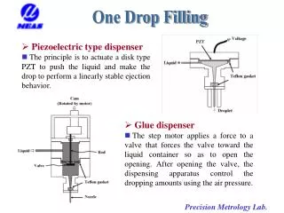
One Drop Filling. Piezoelectric type dispenser The principle is to actuate a disk type PZT to push the liquid and make the drop to perform a linearly stable ejection behavior. Glue dispenser

E N D
One Drop Filling • Piezoelectric type dispenser • The principle is to actuate a disk type PZT to push the liquid and make the drop to perform a linearly stable ejection behavior. • Glue dispenser • The step motor applies a force to a valve that forces the valve toward the liquid container so as to open the opening. After opening the valve, the dispensing apparatus control the dropping amounts using the air pressure.
One Drop Filling • In situ volume measurement of micro droplets • The system developed utilizes a stroboscopic technique to synchronize the triggering of a strobe light and a CCD camera. A steady image of the droplet flying in free space can be captured in situ by the CCD camera. The method of precise volume estimation is based on a rotationally symmetric model of the droplet’s shape. (a) A schematic diagram of a droplet flying in free space (b), (c), (d) Image processing Measured weights of 1000 drops by the subpixel method
Development of chromatic confocal microscope 3-color LED 40X microscope The nominal dimension of the grating: the pitch is 5.0 µm and the height is 2.5 µm. Focus lens Beam splitter Color CCD Beam splitter 60X microscope To get the RG-ratio via the depth response curve could determine the height of work piece.
Monitoring System of Machine Tool Accuracy Degradation • Introduction • During machining, feed force, cutting force and the self weight of machine tool applied to the contact surface, such as the slide way and the linear slide, will cause friction and wear. For improper assembled parts, it will incur loose contact. The accuracy of machine tool will be degraded. • This research is to develop a monitoring system of machine tool accuracy degradation. One object is to develop a software, under known cutting conditions, this software can predict the slider displacements, feed force, reaction force of contact surfaces and wear of slideways. Another to reconstruct the commercial DVD pick-up head to be a precision angular probe. It can measure three angular errors of working stage, and the angular errors can be real-time processed by embedded system, and then angular errors can be displayed on PC that user can know the machining condition. The advantages of this system are high precision, low cost and monitoring immediately, so that can improve industry‘s competitiveness.
Monitoring System of Machine Tool Accuracy Degradation Optical system of DVD pick-up head Residual of angular calibration
Monitoring System of Machine Tool Accuracy Degradation The software of the machine tool accuracy degradation
Principle of the Focusing Probe Disc Voice coil motor and arm springs Objective lens Collimator lens Laser diode Polarization beam splitter and λ/4 plate FES curve Grating Cylindrical lens Quadrant detector Photodiode IC 10um Schematic representation of astigmatic auto-focusing method Basic structure of DVD pick-up head
Measure the Profile of the Scraping Work Piece DVD Laser Probe Objective lens Scraping work piece Moving work plate The micro meter scratches on the scraping work pieces can measure by the DVD probe’s Focus Error Signal can be find out.
The micro CMM • Introduce • Rectangular type of the bridge is always employed in the precision CMM structure for mounting the Z-axis probe. The deformation in the center of the bridge is very critical because of the concentrated load from the spindle. The research proposes a fixed pagoda structure. Under the same dimension and the same spindle load, the maximum deflection at the center of the bridge can be reduced Abbe free in all axes.
2-D high Precision Coplanar Stage • Introduction • Conventional XY stage is stacked up by two linear stages. The Abbe’ error of the lower stage is high. An innovation co-planar stage is thus proposed in this study. • The stage motion is actuated by a ultrasonic motor, the opposite side set the motion sensor of LDGI.
LDGI • Introduction • A compact micro interferometer LDGI (Laser Diffraction Grating Interferometer), could generate interference fringe in half pitch (416.5nm). • With signal interpolation at 360 degree, the resolution can reach to 1nm. • The principle of LDGI with a 1nm resolution, as show in Figure. Through a series polarization phenomenon, the beam will eventually arrive at PD1, PD2, PD3 and PD4. The intensity of each PD can be expressed by:
Tip ball fusing • Introduction • The cleaning feature of a commercial optical fiber fusion splicer is used to manufacture a micro probe. Due to the surface tension , the fiber melt by the arc energy will shrink as a ball at the tip. • Typically , the diameter of tip ball is 300 μm while fusing the tip ball with 125μm fiber. Furthermore, with the melt-drawn technique , the diameter of the tip ball was down to 30 μm. Connecting with the plate of the sensor mechanism , the tip ball fiber can be used as a CMM touch probe. Tip ball with 30 μm diameter made with melt-drawn technique Probe stem Tip ball attached to the CMM probe Fiber probe
Development of method to measure the profile of inside screw • Introduction • Using the motor to drive the mechanism of the probe . • To measure and calculate the x-axis and y-axis displacement by LDGI , and can return to the original condition in the profile of inside screw. LDGI Grating Linear guide Inside screw Motor Stylus Pivot Probe The flow diagram of the system Screw thread To calculate and analysis the Geometry of the Mechanism.