Download
1 / 13
140 likes | 436 Vues
Battery Management System for a Solar Powered Race Car. Joshua Durham Nathan Murdaugh David Trawick. Georgia Institute of Technology School of Electrical and Computer Engineering. Georgia Tech Solar Jackets. April 25 th , 2011. Project Overview.

E N D
Battery Management System for a Solar Powered Race Car Joshua Durham Nathan Murdaugh David Trawick Georgia Institute of Technology School of Electrical and Computer Engineering Georgia Tech Solar Jackets April 25th, 2011
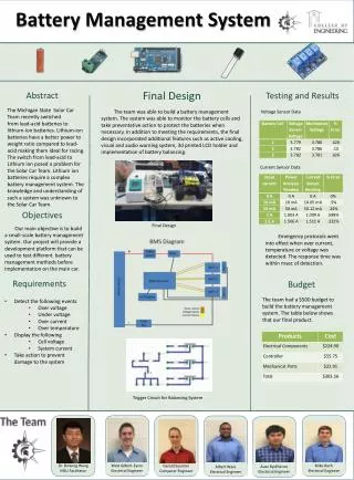
Project Overview • A Battery Management System (BMS) monitors voltage, temperature, and current and balances the batteries, as well as cuts the batteries off when limits are reached • BMS ensures batteries stay within safe charge and temperature limits for maximum efficiency • Meets requirements for World Solar Challenge 2011 • Estimated cost of entire system - $1000
Design Objective Changes • Proposed • Battery Modules with PC boards on either side of the batteries, 3 per pack • Dual power bus • Actual • Accessory board with connector for all the cells • Separate high current and low current boards • Dual power bus not included (but still viable)
Temperature Sensors • Hottest diode has lowest voltage drop across it • Voltage reading corresponds to highest temperature
Ping Response Message • BTON B001 • V00 3.024 V01 3.043 V02 3.034 V03 3.036 • I +20 T 63
Current Progress • Prototype Complete • Code mostly complete, just need to test • Low Current PC board on its way • High Current PC board in progress
Problems/Issues • Accidentally fried an LTC chip by attempting balancing with insufficient resistive load • PIC chip does not have enough RAM for storing all individual voltages and other measurements in their own variables. However, the RS485 message buffer will store all the relevant data.
Budget to Date • Total amount spent for project - ~$240 • Received Differential Amplifiers, PCBs, LTCs, and miscellaneous circuit elements for free • Enough parts to populate 2 boards • Estimated Cost of building a single BMS (both high current and low current board): • Pay for PCB: ~$450 • Free PCB: ~$100
Schedule and Final Delivery • This week: Receive and assemble first PCB • No later than May 5th: Final demonstration and final report • Will deliver two full-size pack BMS along with code, documentation, PCB CAD files, and any extra parts
Recommended Future Work • Using documentation provided, assemble two more BMS • Construct dual power bus diode board if desired • Add mechanical switch and fuse to top of packs