Download
1 / 14
140 likes | 293 Vues
Link Adaptation for PHY SLS calibration. Date: 2014-05-12. Authors:. Motivation. In evaluation methodology document [1], some parameters related to link adaptation have not been decided yet.

E N D
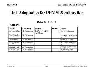
Link Adaptation for PHY SLS calibration Date:2014-05-12 Authors: Jinyoung Chun et.al, LG Electronics
Motivation • In evaluation methodology document [1], some parameters related to link adaptation have not been decided yet. • Based on evaluation, we propose to add some descriptions on link adaptation for MCS selection in evaluation methodology document. Jinyoung Chun et.al, LG Electronics
Link adaptation is to adaptively decide the parameters related to packet transmission such as • Number of spatial stream, MIMO type, MCS level, etc. • This contribution focuses on MCS level adaptation which is done as the following steps: • Step 1. Set the initial SINR value. Or use the feed-backed SINR value if possible. • Step 2. Select the best MCS level using the proper criterion based on modified SINR value1). • Step 3. Make Tx packet using the MCS level and data size according to the MCS level. • From the next slide, we see the underlined issues in the above in detail. Link adaptation 1) Open loop link adaptation: SINR value here has been modified from the SINR value in step 1 by applying SINR margin as follows: SINR margin is increased by Y/(1/X-1)dB when the transmission is succeeded, and SINR margin is decreased by Y dB when the transmission is failed to satisfy Target PER (e.g. X=10%) . Jinyoung Chun et.al, LG Electronics
Option 1. Set to MCS0 • Just put initial MCS level to 0. • Option 2. Distance-based SINR • Calculate the initial SINR based on the distance-based values such as path loss, penetration loss, and etc. • Option 2.1. Interference-free SNR = L= penetration loss + pathloss + shadowing + cable loss – BS gain, Ptx= Transmission Power per tone, N: thermal noise per tone • Option 2.2. Interference-included SINR = ICI = the sum of the worst interference under CCA level from each BSS except its own BSS. Issue 1. Initial SINR setting Jinyoung Chun et.al, LG Electronics
Option 1. Feed-backed SINR (feedback delay) • Calculate SINR of latest frame and modified it using open look link adaptation, and select MCS level for next transmission. • Option 2. Genie SINR (No feedback delay) • Use ‘Genie SINR’ to select MCS level of the current frame. • Notes: • Here, we just consider SINR feedback. More feedback schemes such as sounding, beamforming, MIMO feedback are FFS. Issue 2. SINR feedback method Jinyoung Chun et.al, LG Electronics
Option 1. Goodput-maximizing MCS selection • Find MCS maximizing goodput=(1-PER)* Tx rate [2] • Option 2. X % PER based MCS selection • Find the highest MCS satisfying PER <= X % (X is typically 10) • For both options, we consider the following two cases: • Select MCS every TX events • Select MCS during warm-up time and fix the MCS for all TX events within a drop (Call ‘fixed MCS’) • Note that after some time, PER is saturated to Target PER (X %), then these two options are identical. Issue 3. MCS selection method Jinyoung Chun et.al, LG Electronics
Distance-based SINR (Option 2.2) converges fast both in residential and in outdoor scenarios [See Appendix] Simulation results: initial S(I)NR setting (Assuming SINR margin = 2dB, 10% per based MCS selection) Residential Outdoor Option 1. set to MCS 0 Option 2.2. Interference-included SINR Option 2.1. Interference-free SNR Jinyoung Chun et.al, LG Electronics
Feed-backed SINR (Option 1) has no gain both in residential and outdoor scenarios due to feedback delay • Genie SINR (Option 2) shows large gain in outdoor scenario which is more time-varying in nature. • Genie SINR can be the upper bound of any feedback schemes. Simulation results: SINR feedback method Average throughput per BSS (Assuming SINR margin = 2dB, 10% per based MCS selection, warm-up time 10sec and run time 20sec) Jinyoung Chun et.al, LG Electronics
Goodput maximization MCS selection (Option 1) and 10% PER-based MCS selection (Option 2) show the same results as expected. Fixed MCS shows the similar performance with Full MCS. Simulation results: MCS selection method Average throughput per BSS (Assuming SINR margin = 2dB, Distance-based initial SINR setting, warm-up time 10sec and run time 20sec) Jinyoung Chun et.al, LG Electronics
We propose to add the following descriptions on link adaptation in evaluation methodology document Suggestion on Evaluation Methodology • Link adaptation schemes for MCS selection • Set the initial SINR value as • where • L: pathloss including shadowing, cable loss, penetration loss and antenna gain, • Ptx: transmission power per tone, • N: thermal noise per tone • ICI: sum of worst interference under CCA level from each BSS except its own BSS • SINR is modified from the SINR value in 1) by applying SINR margin (margin is increased by 2/9dB when the transmission is succeeded, and decreased by 2 dB when the transmission is failed. • Select the highest MCS level satisfying PER <= 10% • Make Tx packet using the MCS level and data size according to the MCS level. Jinyoung Chun et.al, LG Electronics
Reference [1] 11-13-1359-00-0hew-hew-evaluation-methodology [2] IEEE 802.11-14/0083r0, “improved-spatial-reuse-feasibility-part-ii”, Broadcom [3] 11-14-0307-00-0hew-phy-calibration-results, Broadcom [4] 11-14-0353, “Suggestion on PHY Abstraction for Evaluation Methodology”, LG Electronics [5] 11-13-1001-06-0hew-simulation-scenarios-document-template Jinyoung Chun et.al, LG Electronics
Appendix. Simulation parameters (1) Jinyoung Chun et.al, LG Electronics
Appendix. Simulation parameters (2) Jinyoung Chun et.al, LG Electronics
In initial S(I)NR setting, the fluctuation of throughput is caused by the unstable PER at the first time of the simulation. Appendix. PER distribution • (Assuming SINR margin = 2dB, 10% per based MCS selection, Outdoor scenario) Residential Outdoor Option 1. set to MCS 0 Option 2.1. Interference-free SNR Option 2.2. Interference-included SINR Jinyoung Chun et.al, LG Electronics