Download
1 / 6
60 likes | 232 Vues
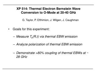
XP 514: Thermal Electron Bernstein Wave Conversion to O-Mode at 20-40 GHz. G. Taylor, P. Efthimion, J. Wilgen, J. Caughman Goals for this experiment: Measure T e (R,t) via thermal EBW emission Analyze polarization of thermal EBW emission Demonstrate >80% coupling of thermal EBWs at ~ 28 GHz.

E N D
XP 514: Thermal Electron Bernstein Wave Conversion to O-Mode at 20-40 GHz G. Taylor, P. Efthimion, J. Wilgen, J. Caughman • Goals for this experiment: • Measure Te(R,t) via thermal EBW emission • Analyze polarization of thermal EBW emission • Demonstrate >80% coupling of thermal EBWs at ~ 28 GHz
Dual Channel 20-40 GHz Radiometer & Steerable Quad-Ridged Horn Provide Orthogonal Polarization Measurements • New instrument will allow • measurement of 20-40 GHz • thermal EBW emission • with ~ 10 ms time resolution • to support Te(R,t) diagnostic • development
XP405 Demonstrated ~ 80% B-X-O Coupling at 16.5 GHz via Thermal EBW Coupling • Full wave coupling model/3-D EBW ray tracing predicts ~ 62-67% coupling in good agreement with measurements • Modeling predicts circularly polarized emission, consistent with measurements Pickup from UCLA reflectometer
AORSA1D Full Wave Coupling Calculations Predict Efficient Coupling at ~ 28 GHz • 28 GHz being considered as operating frequency for megawatt-level NSTX EBWCD system • Experiment will aim to benchmark modeling predictions, including emission polarization at ~28 GHz
Run Plan • Initial measurements in “piggyback” mode to identify optimum antenna alignment for a dedicated experiment • Dedicated experiment will probably use plasma parameters similar to NSTX shot 113544, (Ip = 800 kA, Bo = 4 kG & ~ 2 MW NBI) - would benefit from a relatively long, ~200 ms, Ip flattop • Dedicated experiment requires at least 12 shots • Essential diagnostics: - Thomson scattering Te(R) and ne(R) - Scrape off density profile from ORNL and/or UCLA reflectometer for input to full wave coupling code - EFIT to reconstruct equilibria for 3-D EBW ray tracing
Run Plan - Dedicated Shots Setup & repeat shot similar to 113544 (outer gap ~ 5 cm) until the plasma condition becomes reasonably reproducible. Run EBW radiometer in swept 20-40 GHz mode (2-3 shots) Set radiometer receive frequency ~ 28 GHz (1 shot) Increase outer gap in 5 cm steps to ~ 20 cm, take radiometer data at ~ 28 GHz and 20-40 GHz swept mode for each outer gap (6 shots) 4. In controlled access, rotate antenna by 45 degrees, then run plasma from step 3 that provided maximum EBW signal with radiometer receive frequency ~ 28 GHz and 20-40 GHz swept mode (2 shots) 5. In controlled access, insert quarter wave plate in front of antenna, then run plasma with radiometer receive frequency ~ 28 GHz and in 20-40 GHz swept mode (2 shots)