Download
1 / 45
450 likes | 582 Vues
This lesson provides hands-on training for servicing brakes in 2008 Escape Hybrids and analyzing high voltage problems in Fusion/Milan vehicles. Students will engage with video materials and service publications to answer questions related to brake service procedures, including pad wear rates, systems diagnosis, and troubleshooting various brake-related issues. Emphasis is placed on safety, particularly the importance of removing the service disconnect switch while performing maintenance. Successful completion will enhance understanding of hybrid vehicle brake systems and electrical diagnostics.

E N D
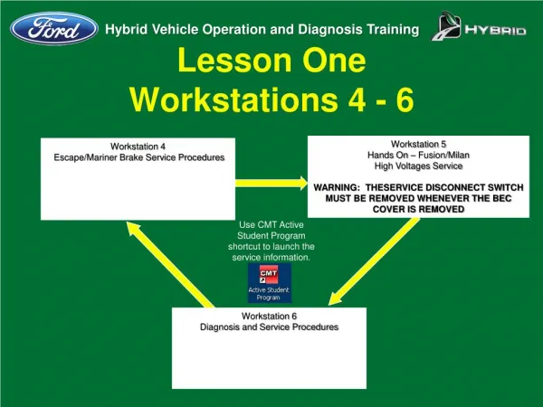
Lesson OneWorkstations 4 - 6 Workstation 5 Hands On – Fusion/Milan High Voltages Service WARNING: THESERVICE DISCONNECT SWITCH MUST BE REMOVED WHENEVER THE BEC COVER IS REMOVED Workstation 4 Escape/Mariner Brake Service Procedures Use CMT Active Student Program shortcut to launch the service information. Workstation 6 Diagnosis and Service Procedures
Lesson OneWorkstation 4 DIRECTIONS: View the Hybrid Brake Service video, then use the video and service publications to answer the questions below.
Lesson OneWorkstation 4 • A 2008 Escape Hybrid is brought to your facility with a customer request for brake service. According to service publications, what actions can be taken to disable the intermittent brake pad application? • The low-voltage battery negative cable and fuses 9 and 18 from the battery junction box (Section 206-03 Brake Pads Hybrid in WSM)
Lesson OneWorkstation 4 • According to service publications, the rear brake pads will wear at approximately what rate when compared to the front brake pads? • The rear brake pads will wear about twice as fast as the front (Section 206-03 Brake Pads - Hybrid in WSM)
Lesson OneWorkstation 4 • When checking the brake fluid in the hybrid master cylinder, what position must the ignition switch be in? • Ignition ON (Section 206-00 Brake System Bleeding – Hybrid)
Lesson OneWorkstation 4 • What component has the function of giving the driver the same feel as pushing on a regular brake pedal, and where is this component found? • The component is the Brake Feel Emulator and it is part of the Actuation Control Unit (ACU) - (1:19 of video)
Lesson OneWorkstation 4 • At what speeds does the regenerative braking slow the vehicle during normal application of the brakes? • Between 70 and 5 mph - - (1:46 of video)
Lesson OneWorkstation 4 • When does the HECU cycle the brake pads? A. When door is unlocked with remote B. Key is turned on C. Door is opened D. All of the above
Lesson OneWorkstation 4 • According to the video, what method can be taken to disable the intermittent brake pad application? • Use of the IDS Brake Pad Replacement selection - (3:34 of video)
Lesson OneWorkstation 4 • What step must be taken before hitting the tick on the IDS for the brake air bleed check? • The brake pedal must be pressed - (4:15 of video)
Lesson OneWorkstation 4 • What pressure is the Rotunda brake bleeder initially set at when performing brake bleeding? • 2 bar or 35 psi - (8:04 of video)
Lesson OneWorkstation 4 • After opening the right front bleeder screw, you press the tick on the IDS. How many times must you depress the brake pedal? • 10 times - (8:25 of video)
Lesson OneWorkstation 4 • What does it indicate when the IDS presents a code OB? • That the pedal needs to be pressed more slowly - (12:56 of video)
Lesson OneWorkstation 4 • What are the major inputs to the brake system? • APP sensor 1,2,3 - TP 1 & 2 - Longitudinal Accelerometer - VSS – Brake Pedal Travel Sensor - ACU (13:57 of video)
Lesson OneWorkstation 4 • What does a DTC C1524 indicate? • That the brake pedal position sensor has not been calibrated or power to the brake pedal travel sensor has been lost - (14:57 of video)
Lesson OneWorkstation 4 • What code indicates that the brake system initialization is incomplete? • DTC C1525 - (16:24 of video)
Lesson OneWorkstation 5 DIRECTIONS: Go to the Fusion/Milan Hybrid classroom vehicle. The customer says there is a “no battery charging” message displayed in the instrument panel. Diagnose this concern and answer the following questions.
Lesson OneWorkstation 5 • Can you verify this concern. Are there any messages being displayed in the message center? • YES – Check Charging System
Lesson OneWorkstation 5 • Does your visual inspection reveal any obvious flaws? • NO
Lesson OneWorkstation 5 • Perform the KOEO self-test, then clear all DTCs. Repeat the KOEO (ALL CMDTCs) self-test and list any CMDTCs found and list the module in which the DTCS are stored? • P0AFA:13-AB - DC/DC, P0AFA:16-AB - DC/DC and Possibly P0AFA:16-2A – ACCM if A/C is on when codes were pulled.
Lesson OneWorkstation 5 • Compare the service publication description for each of the DTC’s listed. Do you find anything in common in these descriptions? • All the DTCs are the result of a low voltage condition
Lesson OneWorkstation 5 • Select the G_INV_V and M_INV_V PID from the TCM Datalogger menu. Turn the ignition to the ON position and pull out the Service Disconnect Switch. What occurs and what does this indicate? • The PIDs indicate the capacitor voltage and show them discharging
Lesson OneWorkstation 5 • Select and perform the pinpoint test that you think is most likely to find the fault? List the pinpoint test and it’s results below, then notify your instructor of your findings. • Students should end up at pinpoint test D for DC/DC converter in Section 413-05 of WSM. They should find the blown HV-LC fuse. Have students complete questions 7-10 then instruct them to remove fuse.
Lesson OneWorkstation 5 • What section of the Workshop Manual contains directions for performing this service? • 414-03
Lesson OneWorkstation 5 • At the beginning of the directions for replacing this component, summarize the WARNING about the service disconnect switch.
Lesson OneWorkstation 5 • Why must the high-voltage/low-current bus bar be removed during this service procedure? • To prevent bending the High-voltage/low-current circuit bus bar
Lesson OneWorkstation 5 • During installation of the component you are directed to replace, what is torque specifications for the high- voltage/high-current positive cable nut and high-voltage/low-current fuse nuts? • High Voltage High Current Cable Nuts 15 Nm (133 lb-in) • High Voltage/Low Current Fuse Nuts 4 Nm (35 lb-in)
Lesson OneWorkstation 6 (Part 1) DIRECTIONS: Use IDS recording L1_WKS6 of the 2010 Milan to answer the following questions.
Lesson OneWorkstation 6 (Part 1) The three PIDS listed below are shown in this recording. Write the IDS definition next to each PID. PID GENMODE Generator Control Mode PID Description RPM TCM Engine Revolutions Per Minute (as measured by the TCM) VSS Vehicle Speed Sensor
Lesson OneWorkstation 6 (Part 1) List the PID readings at approximately 8 seconds into the recording. PID GENMODE Speed PID Description RPM TCM 1290 RPM VSS 6.83 mph
Lesson OneWorkstation 6 (Part 1) List the PID readings at approximately 28 seconds of the recording. PID GENMODE Torque PID Description RPM TCM 0 RPM VSS 14 Kph
Lesson OneWorkstation 6 (Part 1) • Based upon your observations, what does the GENMODE PID indicate when the gasoline engine is running and what does it indicate when the engine is off? • Engine running = Speed • Engine Off = Torque
Lesson OneWorkstation 6 (Part 1) • Review the entire recording. Based upon your observations, what will the GENMODE PID indicate when the gasoline engine is starting and what will it indicate when the engine is shutting down? • Engine starting = Engine Start Normal • Engine shut down = Engine Stop: Enhanced Speed Control
Lesson OneWorkstation 6 (Part 1) • How will viewing these three PIDs when making Datalogger recordings help you during diagnostics? • It will enable the technician to identify the vehicle operating mode (gas or electric), and when the gasoline engine is starting or shutting down
Lesson OneWorkstation 6 (Part 2) DIRECTIONS: A 2008 Escape Hybrid is brought to you with a customer concern of “Hard Steering”.
Lesson OneWorkstation 6 (Part 2) • What type of EPAS system does this vehicle have? • Column Mounted
Perform the diagnosis for the concern using the service publications and the Data Sheet provided by comparing the service publication pinpoint test steps to the pinpoint test steps listed. • The RESULTS COLUMN of the table lists the results of the tests performed, use these results to select the next step that must be performed. • Continue doing this until you have identified the cause of the concern and verified the repair. • NOTE: SOME STEPS IN THE DATA SHEET ARE NOT USED IN THE DIAGNOSIS AND ARE ONLY INCLUDED AS DISTRACTORS. Select only the steps that are required.
Lesson OneWorkstation 6 (Part 2) Result Diagnostic Step Verify the Concern Concern exists as stated by the customer Visual Inspection All OK Connect Scan Tool and Retrieve DTCs DTC B2277 is present View DTC Charts and Descriptions in PC/ED Note Bxxxx View Master Diagnostic Trouble Code (DTC) Index in Workshop Manual Go to Section 211-00 in WSM View PSCM DTC Chart Go to Pinpoint Test B
Lesson OneWorkstation 6 (Part 2) Pinpoint Test B4 Pinpoint Test B5 Voltage on circuit SBB01 is 12.4 V Resistance on Circuit GD116 is OL Result Diagnostic Step Voltage between circuit CBP35 (YE/GY) and ground is 12.6V Pinpoint Test B3 • What should be done to repair this concern? • Repair Circuit GD 116 Pinpoint Test B1 DTC B2277 is present