Download
1 / 44
440 likes | 628 Vues
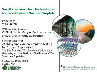
The Effect of Test Specimen Size on Graphite Strength. M P Metcalfe, N Tzelepi and D Wilde ASTM Symposium on Graphite Testing for Nuclear Applications: The Significance of Test Specimen Volume and Geometry and the Statistical Significance of Test Specimen Population

E N D
The Effect of Test Specimen Size on Graphite Strength M P Metcalfe, N Tzelepi and D Wilde ASTM Symposium on Graphite Testing for Nuclear Applications: The Significance of Test Specimen Volume and Geometry and the Statistical Significance of Test Specimen Population 19-20 September 2013, Seattle
Overview of publication Comprises two sections: Section 1 - Case study to support bend strength measurements on small gilsocarbon graphite beams Section 2 – Broad literature review covering tensile, compressive and bend testing plus trending of associated database plus study of consistency across multiple test facilities
Overview of publication Comprises two sections: Section 1 - Case study to support bend strength measurements on small gilsocarbon graphite beams Section 2 – Broad literature review covering tensile, compressive and bend testing plus trending of associated database plus study of consistency across multiple test facilities The talk today will be confined to Section 1
Overview of presentation Background Applicability of ASTM standards Differences between three and four-point bend Elementary beam theory and corrections Potential for shear failure in beams Influence of span with small beams Influence of end effects with small beams Influence of specimen support Effects of friction, contact area and finite beam width Sample volume effects Conclusions
Background (1) When a sampling and measurement programme underwrites the performance of full size graphite components, is there adequate understanding of the influence of material type and specimen size on the measured property?
Background (1) When a sampling and measurement programme underwrites the performance of full size graphite components, is there adequate understanding of the influence of material type and specimen size on the measured property? Specimen sizes may not be compliant with measurement standards. Components being assessed may have sizes considerably larger than both the specimen size specified in the measurement standard and the specimen on which the property measurement is performed. This paper addresses the case where test specimens are small compared with ASTM standard specifications.
Background (2) Sectioned trepanned sample from operating nuclear plant providing a beam for three-point bend strength (6x6x18mm3) Typical beam size used by graphite manufacturer for four-point bend strength (19x19x178mm3)
Background (3) The graphite under investigation: • IM1-24 gilsocarbon nuclear graphite • medium-fine grained graphite with a maximum grain size in the region 0.3-0.5mm • isotropic
Applicability of ASTM standards (1) ASTM C651-11: test method for flexural strength on rectangular parallelepiped geometries using four-point loading (carbon and graphite). Constraints: the minimum dimension should be greater than five times the largest grain dimension, the test specimen length to thickness should be greater than eight and the ratio of test specimen width to thickness should be less than or equal to two.
Applicability of ASTM standards (1) ASTM C651-11: test method for flexural strength on rectangular parallelepiped geometries using four-point loading (carbon and graphite). Constraints: the minimum dimension should be greater than five times the largest grain dimension, the test specimen length to thickness should be greater than eight and the ratio of test specimen width to thickness should be less than or equal to two. For the proposed application, the recommended length to thickness ratio would not be met. Furthermore, application of a four-point loading to a small beam is not experimentally practicable.
Applicability of ASTM standards (2) ASTM C1161-01: test method for flexural strength on rectangular parallelepiped geometries using three-point loading (ceramics). Constraints: the average grain size should be less than 2 percent of the beam thickness (advanced ceramics), for beam lengths of 25, 45 and 90mm, specified widths should be 2, 4 and 8mm respectively and specified depths should be 1.5, 3 and 6mm respectively.
Applicability of ASTM standards (2) ASTM C1161-01: test method for flexural strength on rectangular parallelepiped geometries using three-point loading (ceramics). Constraints: the average grain size should be less than 2 percent of the beam thickness (advanced ceramics), for beam lengths of 25, 45 and 90mm, specified widths should be 2, 4 and 8mm respectively and specified depths should be 1.5, 3 and 6mm respectively. This standard can provide the basis for three-point loading of graphite specimens but its application to small graphite beams needs to be supported by an experimental and theoretical work programme.
Preliminary investigations: four and three-point bend Tests carried out to quantify the difference between four-point bend strength as measured by the graphite manufacturer and three-point bend strength on a small beam. Four-point bend on 19x19x178mm3 beams with a 140mm support span with fixed bearings and 47.5mm load span. Three-point bend on 6x6x18mm3 beams with a 15mm support span with roller bearings. 12 paired beams prepared from three different bricks.
Preliminary investigations: four and three-point bend Tests carried out to quantify the difference between four-point bend strength as measured by the graphite manufacturer and three-point bend strength on a small beam. Four-point bend on 19x19x178mm3 beams with a 140mm support span with fixed bearings and 47.5mm load span. Three-point bend on 6x6x18mm3 beams with a 15mm support span with roller bearings. 12 paired beams prepared from three different bricks. Tests showed an average ratio of four-point to three-point bend strength of 0.77.
Preliminary investigations: sensitivity of four-point bend strength to support and load span Tests carried out to quantify the sensitivity of graphite manufacturers’ four-point bend data to support and load span. 19x19x178mm3 beams with a support/load spans of 140/70, 140/47, 159/53, 114/38 with fixed and roller bearings.
Preliminary investigations: sensitivity of four-point bend strength to support and load span Support span Load span
Preliminary investigations: sensitivity of four-point bend strength to support and load span Tests carried out to quantify the sensitivity of graphite manufacturers’ four-point bend data to support and load span. 19x19x178mm3 beams with a support/load spans of 140/70, 140/47, 159/53, 114/38 with fixed and roller bearings. Support span Load span Small increase in flexural strength as the support and load spans decrease, but differences not statistically significant.
Elementary beam theory Standard formula for the strength (S) of a beam in three-point bending with cross-section bd Good approximation for long beams (large L/d) as local stresses at the supports are small compared to the applied stresses. For short beams, max tensile stress can be split into 2 components: that expressed above plus a term representing local effects near to the point of load application. Solution to corrected stress provided by von Karman and Seewald. (von Karman T and Seewald F, Abhandlung Aerodynamische Institut, Technische Hockschule, Aachen. Vol.7. 1927)
Corrected expression where σxx is the maximum stress at the surface of the beam, c=d/2, l=L/2 and P=p/b and using previous notation,
Corrected expression where σxx is the maximum stress at the surface of the beam, c=d/2, l=L/2 and P=p/b and using previous notation, For a 6×6×18mm3 beam, the theoretical correction would reduce the maximum stress by approximately 7% assuming a span of 15mm.
Will a small beam fail in shear? In a three-point bend test, the shear stress (σxy) is given by Using the corrected expression for maximum tensile stress in bend (σxx )
Will a small beam fail in shear? In a three-point bend test, the shear stress (σxy) is given by Using the corrected expression for maximum tensile stress in bend (σxx ) Ratio must be large to ensure the beam does not fail in shear. In the case of a 6×6×18mm3 beam, σxx / σxy = ~7 which would seem an adequately large margin to ensure tensile failure.
Overview of presentation Background Applicability of ASTM standards Differences between three and four-point bend Elementary beam theory and corrections Potential for shear failure in beams Influence of span with small beams Influence of end effects with small beams Influence of specimen support Effects of friction, contact area and finite beam width Sample volume effects Conclusions
Experimental studies – influence of span Strain-gauged 10×10×60mm3 and 6×6×18mm3 beams with a range of support spans tested in three-point bend. Divide corrected expression by measured strain: Plot reciprocal of measured Young’s modulus (Eel) against the ratio of beam depth to span length (d/L) to evaluate .
Experimental studies – influence of span For a 10×10×60mm3 beam, theoretical and experimental values of are -0.187 and -0.177 respectively (taking account of finite length of strain gauge), corresponding to corrections of -5.6% and -5.3%.
Experimental studies – end effects (1) 13.25mm For a 10×10×60mm3 beam, with fixed span of 33.5mm. First tested with a large overhang 13.25mm. Theoretical and experimental values of are -0.187 and -0.177 respectively (taking account of finite length of strain gauge).
Experimental studies – end effects (2) 13.25mm 1.15mm Beam then cut down to give a short overhang 1.15mm. Small increase in experimental stress correction for the beam with a large overhang (5.1% to 5.3%). Effect may be greater with a smaller beam.
Finite element calculations – influence of span and end effects • 2D finite element model set up to check analytical and experimental findings. • Two sets of boundary conditions investigated: • Zero vertical displacement over a plane through the beam at the support points (inferred from von Karman & Seewald) • Zero vertical displacement at the support points only (defined as actual boundary conditions) • Plane stress conditions were assumed with the elastic modulus set to 10GPa and Poisson’s ratio set to 0.2.
Influence of specimen support Fixed versus roller bearings in bend test arrangement • Study 1 - 19×19×178mm3 beam geometry, four-point bend test configuration with a range of support spans and loading spans. • Average ratio of flexural strengths of 1.06 for fixed to moving bearings. • Differences between fixed and moving bearings statistically significant for a given brick and span combination. • Study 2 - 10×10×60mm3 beam geometry with a three-point bend test configuration. • A significant difference observed between test results using rigid and roller supports with a range of span lengths.
Further finite element studies • Effects of friction • Sensitivity to contact area • Effect of finite beam width 2D half beam model
Further finite element studies • Effects of friction • Based upon a friction coefficient between graphite and steel of 0.1, the ratio of maximum stress under unit force per width without and with friction in a small beam in three-point bend was ~1.06.
Further finite element studies • Effects of friction • Based upon a friction coefficient between graphite and steel of 0.1, the ratio of maximum stress under unit force per width without and with friction in a small beam in three-point bend was ~1.06. • Sensitivity to contact area • Changing the application of force from a point at the centreline of the beam to a finite contact area had no significant effect on the same beam.
Further finite element studies • Effects of friction • Based upon a friction coefficient between graphite and steel of 0.1, the ratio of maximum stress under unit force per width without and with friction in a small beam in three-point bend was ~1.06. • Sensitivity to contact area • Changing the application of force from a point at the centreline of the beam to a finite contact area had no significant effect on the same beam. • Effect of finite beam width • Cross-section of beam distorts as it bends, so contact forces at supports will vary across the beam width. The effect of finite beam width on maximum longitudinal stress was judged to be negligible.
Specimen volume effects (1) Bend strength and uniaxial tensile strength • Measures of strength are known to differ • Graphite failure is believed to initiate at weak points in the matrix • The probability of there being a weak point in the stressed region increases with the size of the stressed region • The stressed region in a bent beam is much smaller than the stressed region in an equivalent size tensile stress specimen • This explains qualitatively why the strength measured in bend is considerably higher than the strength measured in tensile tests • This has been tested experimentally ::
Specimen volume effects (2) Bend strength and uniaxial tensile strength (IM1-24 graphite) • 6×6×18mm3 beams for three-point bend and tensile specimens (ASTM C749-08) with narrowest section 25mm in length and rectangular cross-section of 9.4×6.4mm2 • Ratio of strength measured in three-point bend to strength measured in a tensile test = 1.51 • Ratio depends on the size of the stressed region compared to the grain size, so will differ for different graphite types and different specimen geometries • Non-linear stress-strain curve for a beam will account for some of the difference • peak stress in beam only 0.92 times the linear-elastic value • in a pure tension test, strain is same over cross-section so a non-linear stress-strain curve does not affect the calculated stress
Specimen volume effects (3) Effect of specimen volume on bend strength • 6×6×18mm3 beams with a 15mm support span and a range of beam cross-sections: 8×8mm2, 6×6mm2, 5×5mm2, 4×4mm2 and 3×3mm2
Specimen volume effects (3) Effect of specimen volume on bend strength • 6×6×18mm3 beams with a 15mm support span and a range of beam cross-sections: 8×8mm2, 6×6mm2, 5×5mm2, 4×4mm2 and 3×3mm2 For the geometries tested, flexural strengths are the same within one standard deviation with no evidence for cliff-edge effects.
Conclusions (1) Based upon tests performed on gilsocarbon IM1-24 graphite to support testing of small (6×6×19mm3) beams: • A factor of 0.77 was needed to convert three-point bend strength data for a small beam (using roller bearings) to equivalent manufacturer’s four-point bend strength data. • The sensitivity of four-point bend strength to support and load span was found not to be significant for a manufacturer’s test beam geometry. • The frictional contribution of fixed supports was significant and bend tests should be conducted using roller bearings. • Shear stresses in small beams are low compared to the maximum stress at failure in flexure. • The standard formula from elementary beam bending theory to evaluate stress in a three-point bend tests requires a correction for small beams (reducing the maximum stress by approximately 7% assuming a span of 15mm).
Conclusions (2) Based upon tests performed on gilsocarbon IM1-24 graphite to support testing of small (6×6×19mm3) beams: • Experimental tests on small beams confirm the influence of span and span to beam depth ratio on stress. Corrections based upon theory, experiment and finite element modelling are in good agreement. • Experimental tests to investigate stress in three-point bend beams with and without overhang on the supports show a small reduction in elementary beam theory correction for an extreme case. • Finite element calculations confirm the effects of friction in three-point bends tests on small beams. Also, changing the application of force from a point at the centreline of the beam to a finite contact area had no significant effect on the same beam and the effect of finite beam width on maximum longitudinal stress was judged to be negligible.
Conclusions (3) Based upon tests performed on gilsocarbon IM1-24 graphite to support testing of small (6×6×19mm3) beams: • The stressed region in a bent beam is much smaller than the stressed region in an equivalent size tensile stress specimen, leading to considerably higher measured strengths measured in flexure. • The effect of sample volume on bend strength of a small beam in three-point bend with a fixed support span over a range of beam cross-sections showed flexural strengths to be the same within one standard deviation with no evidence for cliff-edge effects.
Conclusions (3) Based upon tests performed on gilsocarbon IM1-24 graphite to support testing of small (6×6×19mm3) beams: • The stressed region in a bent beam is much smaller than the stressed region in an equivalent size tensile stress specimen, leading to considerably higher measured strengths measured in flexure. • The effect of sample volume on bend strength of a small beam in three-point bend with a fixed support span over a range of beam cross-sections showed flexural strengths to be the same within one standard deviation with no evidence for cliff-edge effects. • While these studies have focused on a single graphite type and test geometry, they provide a framework for qualification of other test programmes on small samples. • NNL test work has provided a sound basis for testing small gilsocarbon beams. • The results should inform users on strength behaviour of other graphites and test geometries.
Acknowledgement The majority of the work reviewed in the accompanying paper is not available in the open literature and so many of the source documents cannot be cited. The authors would like to acknowledge the contributions from internal documents authored by John Payne, Bill Ellis and John Gravenor of the UK National Nuclear Laboratory and Sally Beynon of EDF Energy. The authors would also like to acknowledge EDF Energy and Magnox Limited support for a broader review by the National Nuclear Laboratory of graphite strength from which the more focused review has been based. Thank you for your attention.