Download
1 / 1
10 likes | 160 Vues
Paul McNamara on behalf of the LISA Pathfinder Science Working Team.

E N D
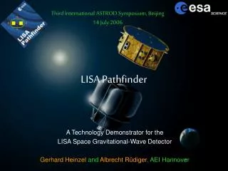
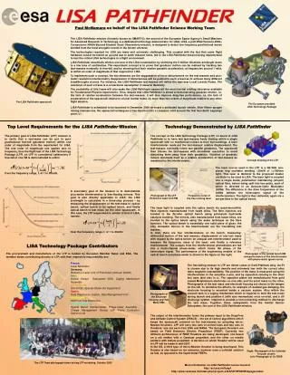
Paul McNamara on behalf of the LISA Pathfinder Science Working Team The LISA Pathfinder mission (formerly known as SMART-2), the second of the European Space Agency’s Small Missions for Advanced Research in Technology, is a dedicated technology demonstrator for LISA. LISA, a joint ESA Horizons 2000+ Cornerstone/ NASA Beyond Einstein Great Observatory mission, is designed to detect low frequency gravitational waves emitted from the most energetic events in the known universe. The technologies required for LISA are many and extremely challenging. This coupled with the fact that some flight hardware cannot be tested on ground due to earth induced noise, led to the LISA Pathfinder mission being implemented to test the critical LISA technologies in a flight environment. LISA Pathfinder essentially mimics one arm of the LISA constellation by shrinking the 5 million kilometre armlength down to a few tens of centimetres. The experiment concept is to prove that geodesic motion can be realised by tracking two test-masses nominally in free-fall, and by showing that their relative parasitic acceleration, at frequencies around 1 mHz, is within an order of magnitude of that required for LISA. To implement such a concept, the key elements are the suppression of force disturbances on the test-masses and pico-meter resolution interferometry. Suppression of disturbances will be pushed to such a level as to achieve many different breakthroughs at once. For instance, the LISA Pathfinder test-masses will define the best ever Local Lorentz Frame. The existence of such a frame is a cornerstone assumption in General Relativity. The availability of this frame will also make the LISA Pathfinder spacecraft the most inertial orbiting laboratory available for Fundamental Physics experiments. Thus, despite that LISA Pathfinder is aimed at demonstrating geodesic motion, i.e. the lack of relative acceleration between the test-masses, it will also improve drag-free performance, i.e. the lack of acceleration of the spacecraft relative to a local inertial frame, by more than two orders of magnitude relative to any other flight mission. LISA Pathfinder is scheduled to be launched in December 2009 on-board a dedicated launch vehicle. After fifteen apogee raising manoeuvres, the spacecraft undergoes a free-injection into a Lissajous orbit around the first Sun-Earth Lagrange point, L1. The LISA Pathfinder spacecraft The European provided LISA Technology Package Top Level Requirements for the LISA Pathfinder Mission Technology Demonstrated by LISA Pathfinder The primary goal of LISA Pathfinder (LPF) mission is to verify that a test-mass can be put in pure gravitational free-fall (geodesic motion) within one order of magnitude from the requirement for LISA. The one order of magnitude rule applies also to frequency, thus the flight test of the LISA Technology Package (LTP) on LPF is considered satisfactory if free-fall of one TM is demonstrated to within Over the frequency range, f, of 1 to 30mHz. The concept of the LISA Technology Package (LTP) on board of LISA Pathfinder is to have two test-masses freely floating within a single spacecraft with no mechanical contact to their surroundings. A laser interferometer reads out the test-masses’ relative displacement. The test-masses nominally follow two parallel geodesics. The spacecraft then follows the test-masses with nanometer resolution to avoid disturbing them away from their geodesics. Violation of geodesic motion manifests itself as a relative acceleration of test-masses as measured by the interferometer. Concept drawing of the LTP The laser source used in the LTP is a Nd:YAG non-planar ring oscillator emitting ~25mW of l=1064nm light. This laser is identical to the proposed master oscillator to be used in LISA. The laser light is coupled into a single mode, polarisation maintaining (sm-pm) optical fibre, before being split into two paths, each of which is directed to an Acousto-Optic Modulator (AOM). The difference in the drive frequencies of the AOMs defines the heterodyne signal of the interferometers. The light is then delivered, again via a sm-pm fibre to the optical bench. A secondary goal of the mission is to demonstrate pico-metre interferometry to free-floating mirrors. This goal is also directly applicable to LISA; the LISA armlength is calculated in a three-step process - by measuring the displacement of the test-mass to optical bench, optical bench to far optical bench, and finally optical bench to test mass (on the other spacecraft). In this case, the LTP requirement is similar to that of LISA, namely: Over the frequency range, f, of 1 to 30mHz Photograph of the LTP Reference Laser Unit EM Frequency noise of the free running laser The laser light is coupled onto the optics bench via quasi-monolithic fibre injectors manufactured from fused silica. The fibre injectors are bonded to the Zerodur optical bench using potassium hydroxide catalysis bonding. The mirrors, also manufactured from fused silica, are bonded to the optics bench using the same technique as the fibre injectors. The optical bench is essentially one solid piece of glass: the only moveable mirrors in the interferometer are the free-falling test masses. In total, there are four interferometers on the bench, measuring: differential motion of the test masses; displacement of one test mass with respect to the optics bench; an unequal arm interferometer used to measure the frequency noise of the laser; and finally a reference interferometer .The outputs from the interferometer photodiodes are fed into a multi-channel phase-meter, which tracks the phase of the heterodyne signal. The performance of the engineering models of the optical bench and phase-meter is shown in the figure on the right. LISA Technology Package Contributors The procurement and manufacture of the LTP is funded by European Member Sates and ESA. The member states contributing directly to LTP, with their respective responsibility are: Photograph of the optical bench EM and performance of the interferometer with phase-meter (green curve) France: Laser Modulator Germany: Reference Laser Unit, LTP Architect (Astrium GmbH) Italy: Inertial Sensor Subsystem (ISS), Caging Mechanism Assembly Netherlands: ISS SCOE (Special Check-Out Equipment) Spain: Data Diagnostics System, Data Management Unit Switzerland: ISS Front End Electronics United Kingdom: Optical Bench Interferometer, Phase-meter Assembly , Charge Management Device, LPF Prime Contractor (Astrium Ltd) The free-falling masses in LTP are 40mm cubes of Gold:Platinum alloy. Au:Pt is chosen due to its high density and extremely low (with the correct alloy ratio) magnetic susceptibility. The position of the mass is measured using the interferometer in the sensitive x-axis, and by capacitive sensing in the other two axes (and also in x). The capacitor plates are manufactured from gold coated Molybdenum electrodes on one side, and the proof mass on the other. Photographs of the test mass and electrode housing are shown in the images on the left. To minimise the effects, for example of residual gas damping, the electrode housing is mounted inside a vacuum system. Also within the vacuum tank is a caging mechanism which is required to hold the test mass during launch and position it (with zero momentum) once on-orbit, and a UV discharge system, required to provide a non-contacting method to discharge the test mass. Together, these subsystems form the Inertial Sensor Subsystem, the core of the LISA Pathfinder mission. Photographs of the Electrode Housing and Test Mass EMs. The output of the interferometer forms the primary input to the Drag-Free and Attitude Control System (DFACS) – the set of control algorithms which keeps the spacecraft centered on the test-masses by actuating micro-Newton thrusters. LPF will carry two sets of control laws and two sets of thrusters; one set each from ESA and NASA. The European thrusters are based on Field Emission Electric Propulsion (FEEP). Currently two different architectures of FEEP thrusters are being developed; one based on a slit emitter with a Caesium propellant, and the other on needle emitters with Indium propellant. A decision on which thruster will be used in LPF will be made in mid-2007. In the US, a third type of micro-Newton thruster is being developed. This thruster is also based on ion emission, however uses a colloidal solution as fuel, as opposed to the liquid metal FEEPs. Right: Photograph of the Colloidal Thruster cluster. Left: Photograph of Cs FEEP. The LTP Team photograph taken during LTP workshop, October 2005 More information on LISA Pathfinder can be found at http://sci.esa.int/lisapf http://www.rssd.esa.int/index.php?project=LISAPATHFINDER&page=index