Accelerator Parameters & Design Workshop - CLIC Interlock System Principles
Join the workshop led by Patrice Nouvel from CERN to explore the critical equipment, post-pulse analysis, interface with acquisition systems, beam permit loop architecture, and more. Dive into requirements and challenges in designing the CLIC Interlock System. Discover the principles of beam permit, redundancy, global analysis, glitch mitigation, and dependability considerations.

Accelerator Parameters & Design Workshop - CLIC Interlock System Principles
E N D
Presentation Transcript
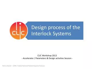
CLIC Workshop 2013 - Accelerator / Parameters & Design activities Session - Patrice Nouvel - CERN / Institut National Polytechnique de Toulouse
Topics Patrice Nouvel – January 2013
Introduction Patrice Nouvel – January 2013
CLIC Interlock System Principles • Critical Equipment: • Look for any equipment failures • Inhibit the next pulse => Beam Permit • Post-Pulse Analysis: • Perform beam quality analysis: assert the next pulse quality • Inhibit the next pulse => Next Cycle Permit Patrice Nouvel – January 2013
Topics Patrice Nouvel – January 2013
Requirements and Challenges Patrice Nouvel – January 2013
Requirements and Challenges Patrice Nouvel – January 2013
Topics Patrice Nouvel – January 2013
Interface with acquisition system CLIC Main Linac X 22 000 CLIC Module (CLIC CDR chap 5.13 Control) Patrice Nouvel – January 2013
Interface with acquisition system ** X 48 Example * • *FEC: Front-End Computer • **ACM: Acquisition and Control Module Patrice Nouvel – January 2013
Beam Permit Loop • Master node: frequency generation • Other nodes (FEC): switch • Redundancy: defined regarding dependability study Design and Functions • Thresholds comparison • Standardized procedure for all data (equipment and beam quality related) • Thresholds managed as Configuration Data • Global analysis • Concentrator • Glitch mitigation, local rules (masking) Patrice Nouvel – January 2013
Architecture Patrice Nouvel – January 2013
Topics Patrice Nouvel – January 2013
Post-Pulse Analysis at CTF3 • Feasibility of Post-Pulse Analysis and first experience • Software only (JAVA application) • Applying the Post-Pulse Analysis Concept to ramp up the beam • Related Document=> EDMS 1182876 Patrice Nouvel – January 2013
Interlock Systems Prototype • Response Time • Beam permit • Post-Pulse analysis • Dependability • Node characteristics (Failure rates) • Extrapolate to determine beam permit loop redundancy Patrice Nouvel – January 2013
Wrap up Patrice Nouvel – January 2013
Thanks for your attention Questions and remarks are welcome
Spare slides Patrice Nouvel – January 2013
CLIC Layout Patrice Nouvel – January 2013
CTF3 Layout Patrice Nouvel – January 2013
Dependability concept definition Adapted from: “Functional Concepts of Dependability”, A.Avizienis, J.C.Laprie, B.Randell MTL Application Note: An introduction to Functional Safety and IEC 61508 Patrice Nouvel – January 2013
Requirements for Control system: Machine Safety • Failure mode: data corruption on critical interlock request • Tolerable riskof 1 catastrophic event every 104years (1.39x10⁻¹³/pulse) • Method 1 (based on operational year 2011) • 48.7% of missions (10h) aborted by critical equipment failures • 6% of missions (10h) aborted by beam instabilities • Probability of Interlock request: 3x10⁻⁷/pulse • Method 2 (based on assumptions on availability) – For comparison (don’t include equipment failure) • 1 instable pulse leads to 10s downtime (interlock and ramp up) • Less 10% downtime is acceptable => 1 instable pulse every 100s • 1% of instable pulses are critical (leading to structure damage) • Probability of Interlock request due to critical instable pulse: 2x10⁻⁶/pulse • Probability of Control system to corrupt data must be lower than: • 4.6x10⁻⁷/pulse (method 1) • 7x10⁻⁸/pulse (method 2 – no equipment request) Patrice Nouvel – January 2013