Download
1 / 16
160 likes | 287 Vues
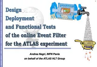
. 0. Design Deployment and Functional Tests of the online Event Filter for the ATLAS experiment. 01 11 010 001 1101 1110 11001 01011 110110 001101 1111111 0111000 11101010 01001110 110111001 000101101 1111010001 0101111100 111101001111 010110000101. TDAQ.

E N D
0 Design Deployment and Functional Tests of the online Event Filter for the ATLAS experiment 01 11 010 001 1101 1110 11001 01011 110110 001101 1111111 0111000 11101010 01001110 110111001 000101101 1111010001 0101111100 111101001111 010110000101 TDAQ Andrea Negri, INFN Pavia on behalf of the ATLAS HLT Group W H Z t
ATLAS T/DAQ system INTRODUCTION DESIGN FUNCTIONAL TESTS DEPLOYMENT CONCLUSIONS ROB ROB ROB RoI LVL2 EF ( ) CM energy 14 TeV Luminosity 1034 cm-2s-1 Collision rate 40 MHz Event rate ~1 GHz Detector channels ~108 1 selected event every million TDAQ Latency Rates Muon Calo Inner • Level 1 trigger • Hardware based • Coarse granularity calo/muon data 40 MHz Pipeline Memories LVL1 ~2 ms ~75 kHz Readout Drivers • Level 2 trigger • Detector sub-region processed • Full granularity for all subdetectors • Fast rejection steering ROD ROD ROD Readout Buffers ~1600 ~10 ms ~2 kHz Event builder network • Event Filter • Full event access • “Seeded” by LVL2 result • Algorithms inherited from offline EF farm ~1000 CPUs ~1 s ~200 Hz Storage: ~ 300 MB/s
Event Filter system: Constraints and Requirements INTRODUCTION DESIGN FUNCTIONAL TESTS DEPLOYMENT CONCLUSIONS SubFarm Input SFI SFI SFI SFI EF SubFarm SFO SFO SFO SFO SubFarm Output EF Read out system • The computing instrument of the EF is organized as a set of independent subFarms, connected to different output ports of the EB switch • Possibility to partition the EF resources and runmultiple concurrent DAQs instances (e.g.: calibration and commissioning purposes) Event builder network • General requirements • Scalability, flexibility and modularity • Hardware independence in order to follow technology trends • Reliability and fault tolerance • Avoid data losses • Could be critical: EF algorithms inherited from the offline ones Storage A common framework for offline and online and similar reconstruction algorithms • Avoids duplication of work • Simplify performance/validation studies • Avoid selection biases • Common database access tools
Design features INTRODUCTION DESIGN FUNCTIONAL TESTS DEPLOYMENT CONCLUSIONS Remote Farm • Each processing node manages its own connection with the SFI and SFO elements that implement the server part ofthe communication protocol • Allows dynamic insertion/removal of sub-farms in the EF or of processing hosts in a sub-farm • Allows geographically distributed implementations • Supports multiple SFI connections: dynamic re-routing in case of SFI malfunction (depends on the network topology) • Avoids single point of failure: a faulty processing host do not interfere with the operations of other sub-farm elements • In order to assure data security in case of event processing problems the design has been based on the decoupling between: Read out system Event builder network SFI SFI SFI SFI SFO SFO SFO SFO Storage data processingdata flow functionalities
DataFlow DataProcessing decoupling INTRODUCTION DESIGN FUNCTIONAL TESTS DEPLOYMENT CONCLUSIONS SFI Incoming Events Node n PT #1 PTIO EFD PT #n PTIO Accepted Events SFO In each EF processing host • Data flow functionalities are provided by the Event Filter Dataflow process that: • Manages the communication with SFI and SFO • Stores the events during their transit in the Event Filter • Makes the events available to • the Processing Tasks that perform the data processing and event selection operations running the EF algorithms in the standard ATLAS offline framework • A pluggable interface (PTIO) allows PTs to access the dataFlow part via a unix domain socket ( ) Data Flow Data Processing
Fault Tolerance: the sharedHeap (1) INTRODUCTION DESIGN FUNCTIONAL TESTS DEPLOYMENT CONCLUSIONS SFI RO map PT #1 PTIO PT #n PTIO SFO • When an event enters the processing node it is stored in a shared memory (sharedHeap) used to provide events to the PTs • A PT, using the PTIO interface (socket) • Requests an event • Obtains a pointer to sharedHeap portion that contain the event to be processed(The PTIO maps this portion in memory) • Processes the event • Communicates back to the EFD the filtering decisions • PT cannot corrupt the events because the map is read only • Only the EFD manages the sharedHeap • If the PT crashes the event is still owned by the EFD,that may assign the event to another PT or force accept it Ev x Node n SharedHeap 10011101010001001001000100010100011110100010010100100010010100010000100010010101011110000010111001100100100100101001101010100010001000100010010001001010001000010001001010101111000001011100110010010010010100110101010001000100010101010101010001011110100110100111000101000111 Ev z Ev y EFD
Fault tolerance: the sharedHeap (2) INTRODUCTION DESIGN FUNCTIONAL TESTS DEPLOYMENT CONCLUSIONS SFI PT #1 PTIO PT #n PTIO SFO • To provide fault tolerance also in case of EFD crash the sharedHeap is implemented as a memory mapped file • The OS itself manages directly the actual write operations avoiding useless disk I/O over-heading • The raw events can be recovered reloading the sharedHeap file at EFD restart • The system could be out of sync only in case of power cut, OS crash or disk failure • these occurrences are completely decoupled from the event types and topology and therefore do not entail physics biases on the recorded data Node n SharedHeap 10011101010001001001000100010100011110100010010100100010010100010000100010010101011110000010111001100100100100101001101010100010001000100010010001001010001000010001001010101111000001011100110010010010010100110101010001000100010101010101010001011110100110100111000101000111 Ev z Ev y Ev x EFD
Flexibility and Modularity INTRODUCTION DESIGN FUNCTIONAL TESTS DEPLOYMENT CONCLUSIONS SFI SFI Node n Implementationexample EFD Input Input Monitoring Sorting PT #1 PT #3 PTIO PTIO Calibration ExtPTs ExtPTs PT #2 PTIO Trash Output Output Output SFO SFO SFO PTIO PTIO PT #b PT #a Calibration data Debugging channel Main output stream • The EFD function is divided into different specific tasks that could be dynamically interconnected to form a configurable EF dataflow network • The internal dataflow is based on reference passing • Only the pointer to the event (stored in the sharedHeap) flows among the different tasks • Tasks that implement interfaces to external components are executed by independent threads (Multi Thread design) • In order to absorb communication latencies and enhance performance
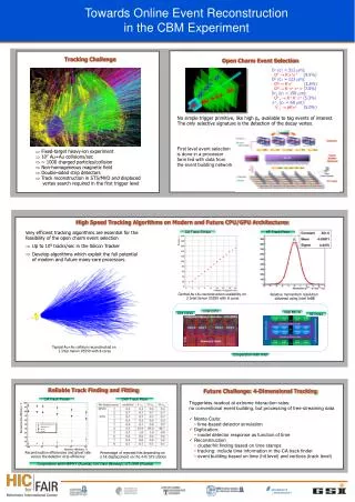
Functional Tests INTRODUCTION DESIGN FUNCTIONAL TESTS DEPLOYMENT CONCLUSIONS Quad xeon 2.5GHz, 4GB 4000 3600 3200 2800 2400 Dummy PT Real PT Memory limit • Verified the robustness of the architecture • Week long runs (>109 events) without crashes or event losses (even randomly killing PTs) • EFD PT communication mechanism scales with the number of running PTs • SFIEFDSFO communication protocol • Exploit gigabit links for realistic event sizes • Rate limitations for small event sizes (or remote farm implementations) • EFD asks for a new event only after the previous one has been received • Rate limited by the round trip time • Improvements under evaluation • Scalability tests carried out on 230 nodes • Up to: 21 subFarms, 230 EFDs, 16000 PTs
INTRODUCTION DESIGN FUNCTIONAL TESTS DEPLOYMENT CONCLUSIONS ATLAS Combined Test Beam
INTRODUCTION DESIGN FUNCTIONAL TESTS DEPLOYMENT CONCLUSIONS Local LVL2 farm 101010100010001001001000100010110 101010100010001001001000100010110 101010100010001001001000100010110 101010100010001001001000100010110 101010100010001001001000100010110 101010100010001001001000100010110 101010100010001001001000100010110 101010100010001001001000100010110 101010100010001001001000100010110 101010100010001001001000100010110 101010100010001001001000100010110 ROS ROS ROS ROS ROS ROS ROS ROS ROS ROS ROS LVL1mu Pixel RPC SCT TRT MDT LAr Tile CSC LVL1calo TGC Contains the LVL2 result that steers/seeds the EF processing pROS Remote Farms: Poland Canada Denmark Event Builder Infrastructure tests only data network (GbE) DFM monitoring run control gateway SFI SFO Local EF farm Storage EF farm @ Meyrin (few Km) Test Beam Layout Muon Calo Tracker
INTRODUCTION DESIGN FUNCTIONAL TESTS DEPLOYMENT CONCLUSIONS Presenter Main Window Test Beam Online Event Processing • Online event monitoring • Online histograms obtained merging data published by different PTs and gathered by a TDAQ monitoring process (the Gatherer) • Online event reconstruction • E.g.: Track fitting • Online event selection • Beam composed of m, p, e • Track reconstruction in muon chamber allowed the selection of m events • Events labelled according to the selection and/or sent to different output streams • Validation of the HLT muon slice (work in progress) • Transfer LVL2 result to EF (via pROS) and decoding • Steering and seeding of the EF algorithm
INTRODUCTION DESIGN FUNCTIONAL TESTS DEPLOYMENT CONCLUSIONS Residuals of segments fit in muon chambers s = 61 mm mm Online Event Processing • Online event monitoring • Online histograms obtained merging data published by different PTs and gathered by a TDAQ monitoring process (the Gatherer) • Online event reconstruction • E.g.: Track fitting • Online event selection • Beam composed of m, p, e • Track reconstruction in muon chamber allowed the selection of m events • Events labelled according to the selection and/or sent to different output streams • Validation of the HLT muon slice (work in progress) • Transfer LVL2 result to EF (via pROS) and decoding • Steering and seeding of the EF algorithm
INTRODUCTION DESIGN FUNCTIONAL TESTS DEPLOYMENT CONCLUSIONS Hits in muon chamber Energy deposition in calo cells Online Event Processing • Online event monitoring • Online histograms obtained merging data published by different PTs and gathered by a TDAQ monitoring process (the Gatherer) • Online event reconstruction • E.g.: Track fitting • Online event selection • Beam composed of m, p, e • Track reconstruction in muon chamber allowed the selection of m events • Events labelled according to the selection and/or sent to different output streams • Validation of the HLT muon slice (work in progress) • Transfer LVL2 result to EF (via pROS) and decoding • Steering and seeding of the EF algorithm
INTRODUCTION DESIGN FUNCTIONAL TESTS DEPLOYMENT CONCLUSIONS ROS Local LVL2 farm ROS pROS data network ROS DFM ROS Local EF farm ROS SFI Online Event Processing • Online event monitoring • Online histograms obtained merging data published by different PTs and gathered by a TDAQ monitoring process (the Gatherer) • Online event reconstruction • E.g.: Track fitting • Online event selection • Beam composed of m, p, e • Track reconstruction in muon chamber allowed the selection of m events • Events labelled according to the selection and/or sent to different output streams • Validation of the HLT muon slice (work in progress) • Transfer LVL2 result to EF (via pROS) and decoding • Steering and seeding of the EF algorithm L2 Result
Conclusions INTRODUCTION DESIGN FUNCTIONAL TESTS DEPLOYMENT CONCLUSIONS • Design: EF designed to cope with the challenging on-line requirements • Scalable design in order to allow dynamic hot-plug of processing resources, to follow technology trend and to allow geographically distributed implementations • High level of data security and fault tolerance via decoupling between data processing and data flow functionalities and the use of memory mapped file • Modularity and flexibility in order to allow different EF data-flows • Functional tests: design validated on different test beds • Proven design robustness, design scalability and data security mechanisms • No design limitations observed • Deployment on test beam setup • Online event processing, reconstruction and selection • Online validation of the HLT muon full slice