Download
1 / 34
350 likes | 577 Vues
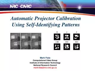
Automatic Projector Calibration with Embedded Light Sensors. Johnny C. Lee 1,2 Paul H. Dietz 2 Dan Maynes-Aminzade 2,3 Ramesh Raskar 2 Scott E. Hudson 1. 1 Carnegie Mellon University 2 Mitsubishi Electric Research Labs 3 Stanford University Santa Fe, NM UIST 2004.

E N D
Automatic Projector Calibration with Embedded Light Sensors Johnny C. Lee1,2 Paul H. Dietz2 Dan Maynes-Aminzade2,3 Ramesh Raskar2 Scott E. Hudson1 1Carnegie Mellon University 2Mitsubishi Electric Research Labs 3Stanford University Santa Fe, NM UIST 2004
Our Approach • - Embed light sensors into the target surface • optical fibers channel light energy from each corner to sensors • USB connection to the PC • White front surface hides fibers and acts as a light diffuser
Calibration Demo Demonstration of calibration process
Gray Code Patterns • Binary sequence where only 1-bit changes from one entry to the next. • Robust spatial encoding property • Frequently used in Range-Finding systems
Binary Gray 0000 0001 0010 0011 0100 0101 0110 0111 1000 1001 1010 1011 1100 1101 1110 1111 0000 0001 0011 0010 0110 0111 0101 0100 1100 1101 1111 1110 1010 1011 1001 1000
Binary Gray 0000 0001 0010 0011 0100 0101 0110 0111 1000 1001 1010 1011 1100 1101 1110 1111 0000 0001 0011 0010 0110 0111 0101 0100 1100 1101 1111 1110 1010 1011 1001 1000
Scalability and Robustness • Pattern count = log2(pixels) • Constant time with respect to # of sensors • Decoding location requires only one XOR operation per location bit (cheap & fast) • Robust against inter-pixel sensor positioning • Robust against super-pixel size sensors • Accurate to the nearest pixel when in focus • Degrades gracefully in under defocusing • Strong angular robustness
Angular Robustness & Mirrors Demonstration Video
Optical Path Optical path between the projector and the sensor does not need to be known. Pixel location of a sensor can be found so long as there exists a path. Additional sensors in the target surface can increase robustness to partial occlusion.
Application Demonstrations Demonstration Video
Research Applications Digital Merchandising, MERL Everywhere Displays, IBM ShaderLamps, projector AR, UNC/MERL
Other Applications • Cheap, light-weight displays • Projector array stitching • data walls • planetariums • Redundant projector alignment • shadow reduction • stereoscopic displays • increasing brightness • - high-dynamic range display
Trade Offs • Digital correction inherently sacrifices pixels and resamples the image. • Image filtering • Higher resolution projectors • Pan-Tilt-Zoom projectors (preserve pixel density) • Optical correction • Requires instrumented surface • Not a problem for some high QoS applications • Removable/reusable wireless calibration tags
Future Work • Interactive Rates - Movable Screens • High speed projection (DLP) • n-ary and RGB Gray Codes • Adaptive Patterns • Imperceptible calibration • High speed steganography • Infrared • Multiple projectors • Smart rooms • 3D positioning
Concluding remarks • Robust • Fast • Accurate • Low-Cost • Scalable • Applicable in HCI and out
Thanks! Contact Info Johnny Chung Lee johnny@cs.cmu.edu Haptic Pen: A Tactile Feedback Stylus for Touch Screens Wednesday 3pm session
Homography • Automatically flips image in the presence of mirrors. • Works with OpenGL and DirectX matrix stacks for real-time warping on low-cost commodity hardware. • Warping extends beyond the bounds of the sensors (internal feature registration, characterization) • If more than 4 sensors are use, sub-pixel accuracy can be achieved through best-fit solutions Four sensor coordinates are used to compute a homography – (loosely) a transformation between two coordinate spaces.
vs. Camera Based Approach • Standard computer vision problems • Background separation • Variable lighting conditions • Material reflectance properties • Non-planar/Non-continuous surfaces can be difficult • Accurate registration to world features requires high resolution cameras • Expensive (and high-speed is even more expensive) • High-computational overhead (Pentium vs. PIC) • Rigid camera-projector geometry • Requires calibration • Zooming may be problematic • Not as flexible • Projector stitching/Redundancy • ShaderLamps/Non-planar surfaces