Download
1 / 66
1.17k likes | 2.6k Vues
The Optical Fiber and Light Wave Propagation. Xavier Fernando Ryerson Comm. Lab. The Optical Fiber. Fiber optic cable functions as a ”light guide,” guiding the light from one end to the other end. Fiber categories based on propagation: Single Mode Fiber (SMF) Multimode Fiber (MMF)

E N D
The Optical Fiber and Light Wave Propagation Xavier Fernando Ryerson Comm. Lab
The Optical Fiber • Fiber optic cable functions as a ”light guide,” guiding the light from one end to the other end. • Fiber categories based on propagation: • Single Mode Fiber (SMF) • Multimode Fiber (MMF) • Categories based on refractive index profile • Step Index Fiber (SIF) • Graded Index Fiber (GIF)
n1 n2 Step Index Fiber • Uniform ref. index of n1 (1.44 < n1 < 1.46) within the core and a lower ref. index n2 in the cladding. • The core and cladding radii are a and b. Typically 2a/2b are 8/125, 50/125, 62.5/125, 85/125, or 100/140 µm. • SIF is generally made by doping high-purity fused silica glass (SiO2) with different concentrations of materials like titanium, germanium, or boron. n1>n2
Different Light Wave Theories • Different theories explain light behaviour • We will first use ray theory to understand light propagation in multimode fibres • Then use electromagnetic wave theory to understand propagation in single mode fibres • Quantum theory is useful to learn photo detection and emission phenomena
Refraction and Reflection When Φ2 = 90, Φ1 = Φc is the Critical Angle Φc=Sin-1(n2/n1 ) Snell’s Law: n1 Sin Φ1 = n2 Sin Φ2
Step Index Multimode Fiber Fractional refractive-index profile
Single Mode Step Index Fiber Only one propagation mode is allowed in a given wavelength. This is achieved by very small core diameter (8-10 µm) SMF offers highest bit rate, most widely used in telecom
Refractive Index Profile of Step and Graded Index Fibers n1 n1 Step Graded n2 n2 a b a b n = n =
Step Index Multimode Fiber • Guided light propagation can be explained by ray optics • When the incident angle is smaller the acceptance angle, light will propagate via TIR • Large number of modes possible • Each mode travels at a different velocity • Modal Dispersion • Used in short links, mostly with LED sources
Graded Index Multimode Fiber • Core refractive index gradually changes towards the cladding • The light ray gradually bends and the TIR happens at different points • The rays that travel longer distance also travel faster • Offer less modal dispersion compared to Step Index MMF
Skew rays Skew rays circulate around the core and increase the dispersion
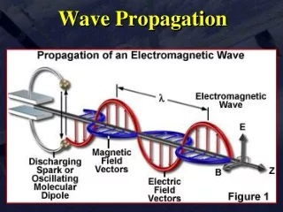
Maxwell’s Equations In a linear isotropic dielectric material with no currents and free of charges, ……..(1) (Faraday’s Law) ……….(2) (Maxwell’s Faraday equation) ……….(3) (Gauss Law) ……….(4) (Gauss Law for magnetism) Taking the curl of (1) and using and …….(5) The parameter ε is permittivity and μ is permeability.
Maxwell’s Equations But from the vector identity ……(6) Using (5) and (3), …….(7) Similarly taking the curl of (2), it can be shown ………(8) (7) and (8) are standard wave equations. Note the Laplacian operation is,
Maxwell’s Equation • Electrical and magnetic vectors in cylindrical coordinates are give by, .…..(9) ……(10) • Substituting (9) and (10) in Maxwell’s curl equations ….(11) ….(12) ….(13)
Maxwell’s Equation • Also ----------(14) ----------(15) ----------(16) • By eliminating variables, above can be rewritten such that when Ezand Hzare known, the remaining transverse components Er , Eφ, Hr , Hφ, can be determined from (17) to (20).
Maxwell’s Equation …………..(17) …………..(18) …..........(19) .………… (20) Substituting (19) and (20) into (16) results in ….…(21) …….(22)
Electric and Magnetic Modes Note (21) and (22) each contain either Ez or Hz only. This may imply Ez and Hz are uncoupled. However. Coupling between Ez and Hz is required by the boundary conditions. If boundary conditions do not lead to coupling between field components, mode solution will imply either Ez =0 or Hz =0. This is what happens in metallic waveguides. When Ez =0, modes are called transverse electric or TE modes When Hz =0, modes are called transverse magnetic or TM modes However, in optical fiber hybrid modes also will exist (both Ez and Hz are nonzero). These modes are designated as HE or EH modes, depending on either H or E component is larger.
Wave Equations for Step Index Fibers • Using separation of variables ………..(23) • The time and z-dependent factors are given by ………..(24) • Circular symmetry requires, each field component must not change when Ø is increased by 2п. Thus …………(25) • Where υ is an integer. • Therefore, (21) becomes ….(26)
Wave Equations for Step Index Fibers • Solving (26). For the fiber core region, the solution must remain finite as r0, whereas in cladding, the solution must decay to zero as r∞ • Hence, the solutions are • For r< a, Where, Jv is the Bessel function of first kind of order v • For r> a, Where, Kv is the modified Bessel functions of second kind
Bessel Functions Second kind Bessel Functions First Kind Modified Bessel Second kind Modified Bessel first kind
Propagation Constant β • From definition of modified Bessel function • Since Kv(wr) must go to zero as r∞, w>0. This implies that • A second condition can be deduced from behavior of Jv(ur). Inside core u is real for F1to be real, thus, • Hence, permissible range of βfor bound solutions is
Meaning of u and w Inside the core, we can write, • Both u and w describes guided wave variation in radial direction • u is know as guided wave radial direction phase constant (Jn resembles sine function) • w is known as guided wave radial direction decay constant (recall Kn resemble exponential function) Outside the core, we can write,
V-Number (Normalized Frequency) Define the V-Number (Normalized Frequency) as, All but HE11 mode will cut off when b = 0. Hence, for single mode condition, Define the normalized propagation const b as,
At r = wo, E(Wo)=Eo/e Mode-field Diameter (2W0) In a Single Mode Fiber, Typically Wo > a
Cladding Power Vs Normalized Frequency Modes Vc = 2.4
Power in the cladding Lower order modes have higher power in the cladding larger MFD
Major Dispersions in Fiber • Modal Dispersion: Different modes travel at different velocities, exist only in multimode fibers • This was the major problem in first generation systems • Modal dispersion was alleviated with single mode fiber • Still the problem was not fully solved
Dispersion in SMF • Material Dispersion: Since n is a function of wavelength, different wavelengths travel at slightly different velocities. This exists in both multimode and single mode fibers. • Waveguide Dispersion: Signal in the cladding travels with a different velocity than the signal in the core. This phenomenon is significant in single mode conditions. Group Velocity (Chromatic) Dispersion = Material Disp. + Waveguide Disp.
Modifying Chromatic Dispersion GVD = Material Disp. + Waveguide dispersion • Material dispersion depends on the material properties and difficult to alter • Waveguide dispersion depends on fiber dimensions and refractive index profile. These can be altered to get: • 1300 nm optimized fiber • Dispersion Shifted Fiber (DSF) • Dispersion Flattened Fiber (DFF)
Different WG Dispersion Profiles WGD is changed by adjusting fiber profile
Dispersion Shifting/Flattening (Standard) (Low Dispersion throughout) (Zero Disp. At 1550 nm)