TOF0 and TOF1 time calibration
200 likes | 347 Vues
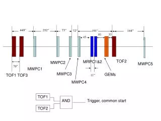
TOF0 and TOF1 time calibration. Yordan Karadzhov. Absolute Time Calibration Method. General d escription of the TOF DAQ setup

TOF0 and TOF1 time calibration
E N D
Presentation Transcript
TOF0 and TOF1 time calibration Yordan Karadzhov Y. Karadzhov, MICE CM25
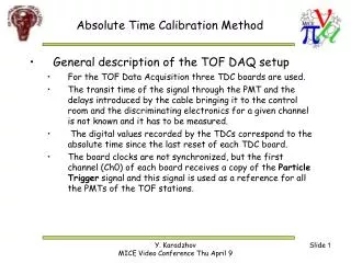
Absolute Time Calibration Method • General description of the TOF DAQ setup • The transit time of a signal through the PMT and the delays introduced by the cable bringing it to the control room and by the discriminating electronics for a given channel is not known and it has to be measured. • The digital value recorded by the TDCs corresponds to the absolute time since the latest reset of each TDC board. • The board clocks are not synchronized, but the first channel (Ch1) of each board receive a copy of the Particle Trigger Request signal and this signal is used as a reference for all the PMTs of the TOF stations. • Recorded TDC value can only make sense if referred to the Particle Trigger Request time. • Which PMT (channel) delivers the trigger depends on the position on the hit; therefore the delay of the Particle Trigger Request signal depends on the position of the hitas well. #)Detailed description of the method is available in MICE Note : http://mice.iit.edu/micenotes/public/pdf/MICE0251/MICE0251.pdf Y. Karadzhov, MICE CM25
Absolute Time Calibration Method Y. Karadzhov, MICE CM25
Absolute Time Calibration Method • Time of the signal of a given PMTmeasured by the TDC: PMT(TDC) time Time of the hit Distance between the position of the hit and the PMT Cable delay Speed of light in the scintillator • Particle Trigger Request signal time for a given combination of slabs (pixel). We assume the signal is given always by one and the same PMT for a given pixel. Trigger(TDC) time Combined cable delay and light travel time Y. Karadzhov, MICE CM25
Absolute Time Calibration Method • For a given combination of slabs (a pixel) we have where the bracket means the average over all the particles hitting the pixel ij.We will call this constant t0iij. Y. Karadzhov, MICE CM25
Absolute Time Calibration Method Average light travel time is the average time it takes of the light to travel between two pixels (e.g. ij andik ). For a horizontal slab we have Indexes S and N mean South and North PMT. • For a given slab in TOF0 we have 10 light travel times Δtij→ik, i.e. 200 light travel times for TOF0. Y. Karadzhov, MICE CM25
Absolute Time Calibration Method Pixel 4 Pixel 5 Relative trigger delays. In a given slabthe difference between the t0 constants is given by Average light travel time Difference between the trigger delays in pixels ij and ik • If we choose agiven pixel i0j0as a reference we can define a new calibrationconstant - the relative trigger delayΔTtrigger jl Pixel 6 Y. Karadzhov, MICE CM25
Absolute Time Calibration Method • Calibration constants for TOF0 : • 40 t0iijconstants (one per PMT/channel) for TOF0 : the difference between the delay in channel i (delays in the slab material, PMT, cables, …)and the delay of the channel which delivers the trigger when pixel ij is hit. • 100 Relative Trigger Delays Δ Ttr ij (one per pixel) for TOF0 : the difference between trigger delay (the delay in the channel which is delivering the trigger) from pixel ij and the trigger delay for a pixel used as a reference. Y. Karadzhov, MICE CM25
Absolute Time Calibration Method For the station which is not the trigger source (TOF1) if the pixel lk in TOF0 is hit (gives the trigger) and the pixel mn in TOF1 is hit, for the South PMT of slab m in TOF1, if we select only positrons, we have • We have 28 t0 constants for TOF1. No Trigger delay correction Y. Karadzhov, MICE CM25
Absolute Time Calibration Method • Calibration constants for TOF1 and TOF2 : • 28 t0mconstants (one per PMT/channel) for TOF1 : the delay in channel m of TOF1. • 40 additional t0kconstants (one per PMT/channel) will be needed for TOF2. Y. Karadzhov, MICE CM25
TOF0 time resolution Time difference between the vertical and horizontal slabs in the same station is used to measure the time measurement resolution after the calibration. The resolution on the difference in the calibrated pixels of TOF0 is ~105 ps. This translates into ~ 52 ps precision of the averaged two-plane measurement. Y. Karadzhov, MICE CM25
TOF1 time resolution Measured resolution for the calibrated pixels in TOF1 ~ 136 ps. This translates into ~ 68 ps precision of the averaged measurement. Y. Karadzhov, MICE CM25
Time Walk Correction • Leading edge discriminators introduce a dependence of the measured time on the collected charge (time walk). • To obtain the time walk correction one measures the difference between the time measured by the PMT and a reference time. • The dependence of this time difference on the PMT pulse height is approximated (see the formula) and used as a correction. • The reference time is given by a PMT in the other plane of the Station and the time walk effect in the measurement of the reference time is suppressed by an offline constraint on the ADC pulse height in the reference PMT. • Precision in our case is limited by statistics (events are concentrated in a small region). Y. Karadzhov, MICE CM25
Bad slab • Main fraction of the events are in a region where Time Walk effect is stronger. Y. Karadzhov, MICE CM25
Good slab • Main fraction of the events are in a region where Time Walk effect is not so strong. Y. Karadzhov, MICE CM25
How reliable is the absolutetime calibration ? • The resolution in a given pixel can be measured before the absolute time calibration • The expected total resolution of the detector can be calculated by the formula , where σi is the resolution in pixel i, Ni is the number of events in pixel i and Ntot is the total number of event. Y. Karadzhov, MICE CM25
TOF0 Predicted Resolution vs. Real Resolution • In TOF0 predicted Resolution is 51.2 ps and measured is 52.3 ps Worst pixel Best pixel Y. Karadzhov, MICE CM25
TOF1 Predicted Resolution vs. Real Resolution • In TOF0 predicted Resolution is 64.2 ps and measured is 68.1 ps Best pixel Worst pixel Y. Karadzhov, MICE CM25
Demonstration of the capabilities of the TOF system Y. Karadzhov, MICE CM25
Conclusions • 300 MeV/c electron beam is the best candidate for the new calibration. • TW correction is critical for the precision of the time measurement. • Systematic errors in the calibration of TOF1 are not very well understood. Y. Karadzhov, MICE CM25