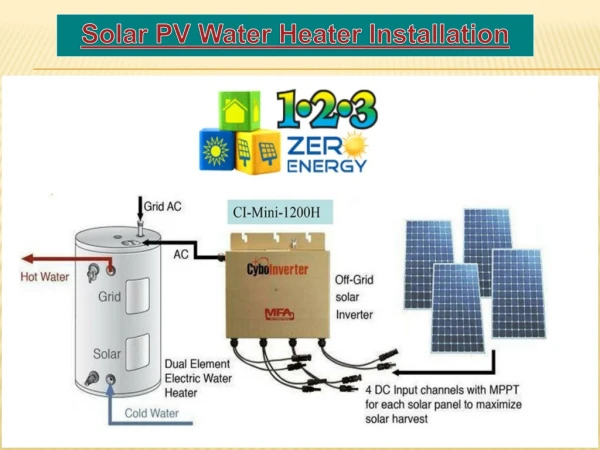
PV System Installation
PV System Installation. Photovoltaic Power Systems Resource Book – Slide Show Unit 8 . Getting there. If a trip to site took 8 hours … and involved all of this … What would you want to make sure of before you left?.

PV System Installation
E N D
Presentation Transcript
PV System Installation Photovoltaic Power Systems Resource Book – Slide Show Unit 8 (C) BIT Renewable Energy Centre
Getting there If a trip to site took 8 hours … and involved all of this … What would you want to make sure of before you left? Many PV systems are installed in remote locations. Travelling time can be long, and accessibility can sometimes be difficult. Good planning and thorough preparation is essential, since a trip home is not an option. (C) BIT Renewable Energy Centre
Array Frames and Mounting (1) The most common choice for PV array frames is aluminium angle or channel. It is light, strong, and easy to work with. The design of the array frame should allow for easy installation and maintenance, as well as structural strength. It is a simple matter to drill extra holes to allow the frames to be tilted up for easy access to the junction boxes. (C) BIT Renewable Energy Centre
Array Frames and Mounting (2) Free standing arrays require greater structural strength, and are commonly made of galvanised steel. Structures such as these, including the footings, must be certified by a structural engineer. The array above is at the UNSW Little Bay facility and the image at top right is part of a 6 kW array at a National Park Rangers Station on Moreton Island, Qld. (C) BIT Renewable Energy Centre
Array Frames and Mounting (3) Timber is also a useful frame or support material. This array frame was made from second hand steel shelving pieces. Multiple holes drilled in the support struts allow tilt angle to be varied seasonally. At a minimum, a summer and a winter position can be used. The timber poles provide a very solid structure for mounting. Note the use of aerial cable from this array. (C) BIT Renewable Energy Centre
Array Frames and Mounting (4) Sometimes, the situation calls for drastic measures. When the site is completely surrounded by trees, going up may be the only way of getting adequate sunlight. At this telecommunications site in Central Queensland, available land was very limited, and the neighbouring landowner would not allow any tree clearing. The solution was an array mounted 12 metres above ground level, complete with platform for installation and maintenance access. This raised another issue – that of the distance between the array and the battery. Heavier cable had to be used to keep voltage drop within acceptable limits. (C) BIT Renewable Energy Centre
Array Cabling Array wiring should be completely enclosed in conduit. Unenclosed wiring will experience UV degradation even in shaded areas such as under a PV module, because of diffuse and reflected radiation. (C) BIT Renewable Energy Centre
Battery Installation (1) In the past, many batteries have been installed in ways that would not be acceptable today. Increasing emphasis is being put on Standards – and rightly so because of the potential danger batteries pose. The battery installation above looks makeshift – yet it may have been a permanent arrangement !! Good points: mounted off the ground and level; location looks well ventilated. Bad points: no safety signage; no acid tray; no acid proof coating on stand; temporary cabling (risk of spark on connect or disconnect); cable not enclosed in conduit (no mechanical protection); accessible by unauthorised people, including children; not vermin-proof or dust-proof; no safety equipment … This manner of installation is clearly unacceptable today. (C) BIT Renewable Energy Centre
Battery Installation (2) Compare the image on the previous page, to these telecomms systems, which follow Australian Standards very closely. Ventilation to A.S.; Dust Filter Safety signage Double tiered rack with row spacing according to A.S. Width of aisles meets A.S. Acid proof flooring and paint Lockable battery room. (C) BIT Renewable Energy Centre
Battery Installation (3) This battery installation, at UNSW Little Bay, also conforms to Australian Standards. Note the use of a single acid drip tray on the floor, beneath both tiers of battery. This installation, while meeting many of the requirements, including very good ventilation, does not provide separation between the batteries and the contactors, switches and other arc producing equipment in the system. (C) BIT Renewable Energy Centre
Battery Installation (4) Do these installations meet Australian Standards? Consider access to the batteries, support and protection of cabling, ventilation, spill containment… (Right hand battery is built from 8 V monoblocks. (C) BIT Renewable Energy Centre
PV Installations - balance of system components Suncycle wet cells – 24 V series string (12 x 2V cells). Well ventilated and clean accommodation, also note terminal covers. Left hand battery may be against hot wall. The battery cables have not yet been installed. (C) BIT Renewable Energy Centre
PV Installations - balance of system components A well designed and correctly installed diesel generating set - note ventilation, cleanliness, flexible exhaust pipe section and vibration mounts. Cable support however leaves a bit to be desired! It would be preferable to run the cable along the ground and protect it with a steel cap. (C) BIT Renewable Energy Centre
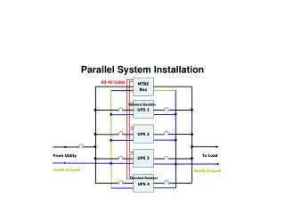
PV Installations - balance of system components A complex RAPS distribution and control system. However the wiring and components are neatly installed, and would meet standards. Another distribution system, but note the reduction in exposed cabling due to cables being run between components butted up against each other. (C) BIT Renewable Energy Centre
PV Installations - what NOT to do A classic “do-it-yourself” job!Very unsafe and illegal! (C) BIT Renewable Energy Centre
PV Installations - what NOT to do The previous system after improvement by a team of TAFE students. However, this photo was taken in the late 1980’s, and the system would not meet current standards. (C) BIT Renewable Energy Centre
Boating The installation of PV systems on boats, as in other vehicles, often means working in restricted spaces, with custom built equipment accommodation. Battery storage Super-energy efficient fridge Inverter, PV regulator Control panel – integrated with radio equipment controls. Circuit breakers (C) BIT Renewable Energy Centre
PV system for ute This ute used 2 64 W modules to provide power for a small refrigerator and for lighting on camping trips. It was also used on a complete trip around Australia! Battery storage was 2 200 Ah Alco deep cycle batteries (modified SLI type). The PV modules also charged the vehicle’s start battery, and the two batteries were isolated from each other by diodes. The Engel refrigerator was the main system load, so care was taken to ensure good ventilation (fan assisted) in the fridge box to keep the unit operating as efficiently as possible. (C) BIT Renewable Energy Centre
Household PV Systems Equipment accommodation for household systems can also be tight. Few clients have a purpose built room for the power system equipment. MPPT regulators A.C. switchboard Sine wave Inverter D.C. control board Genset controller Battery charger Battery (C) BIT Renewable Energy Centre
Packaged Systems Installation is simplified greatly by the use of “packaged” systems. These are standardised systems which are pre-assembled and tested in a workshop, then simply taken to site, bolted down and connected up. A “pyramid power” system. Visible are the control cubicle and half of the battery. The other two sections house the rest of the battery and a small petrol genset. The array tracks the sun, and is shown in the horizontal position. “Containerised” system. Shipping containers have the advantage of low cost, robust transportability and insulated walls. Packaged system. (C) BIT Renewable Energy Centre
Note! Further detail on PV array installation is contained in another slide show. (C) BIT Renewable Energy Centre