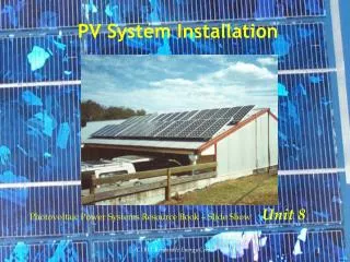
PV System Design and Installation
PV System Design and Installation. LO 8 – PV Electrical Design. Electrical Design (8% of test questions). Task/Skill 8.1. Determine series/parallel PV array arrangement based on module and inverter specifications 8.2. Select BOS components appropriate for specific system requirements

PV System Design and Installation
E N D
Presentation Transcript
PV System Design and Installation LO 8 – PV Electrical Design
Electrical Design (8% of test questions) Task/Skill 8.1. Determine series/parallel PV array arrangement based on module and inverter specifications 8.2. Select BOS components appropriate for specific system requirements 8.3. Determine voltage drop between major components
PV Array String Sizing • Step 1 • Determine inverter “constraints” • Maximum DC Input Voltage • MPPT Range
Determine OperatingTemperature Conditions • Step 2 • a) For maximum number of modules in a string use the “Coldest Record Temperature” • b) For minimum number of modules in a string need Average Monthly High Temperature plus 30 degree F Avg High Tempurature Record Low Tempurature
Temperature conversion formulas Tc = (5/9)*(Tf-32) Tf = (9/5)*Tc+32 Tc = temperature in degrees Celsius Tf = temperature in degrees Fahrenheit
Determine Maximum String Size • Step 3 • Apply NEC Voltage Temperature Correction Factor to Open Circuit Voltage (Voc) of PV Module • PV module string size must not exceed maximum DC input voltage (usually 500V or 600V). • In Albany, Record Low Temp = -22 F, therefore must use a temperature correction factor of 1.25 • Vmax string = Voc x Temp x Modules in String • Correction • Factor Reference Class Book by Dunlop
Determine Minimum String Size Step 4 Determine Minimum String Size Apply Manufacturer’s Temp Correction Factor to Maximum Power Point Voltage (Vmp) Make sure that Vmp (temp corrected) stays within MPPT tracking range of inverter. For example, temperature correction factor for SunPower Modules is -0.1368 V Vmin = Vmp + (High Temp – 25 C) x Modules in String Where, High Temp = Average High Temperature + 17 C Reference Class Book by Dunlop
Determine Number of Strings necessary to achieve PV array capacity requirements (kW) Step 5 Power = Series String Voltage (Vmp) x Parallel String Current (Imp) Where, Parallel String Current = Number of Strings in Parallel
Choose inverter In general, PV array DC input (watts) can be up to 1.2 x Inverter AC output (watts) rating in Upstate New York Max Number <I max DC input of inverter of strings I max string current For example, using SunPower SPRm 5000 inverter, using 230W module (Imp = 5.61 amps) Max Number <21 amps = 3.74 strings of string 5.61 amps PV Array Size Maximum (3 strings x 8 modules) = 24 x 230W = 5.52 kW
Wire Sizes Look at wire layout board in HVCC lab
Voltage Drop Calculations Voltage Drop (volts) = Current (amps) X Resistance (ohms) V = I x R % Voltage Drop = 0.2 x D x I x R V D= One-way distance in feet I= Current (use Imp for solar circuits) R= Resistance of conductor (Ohms/1,000 feet). From NEC Chapter 9, Table 8 V= Voltage (use Vmp x the # of modules) Typically design for less than 1 % voltage drop NEC Requirements Maximum from Service to the Load of 5% Maximum from final overcurrent protection device to the load of 3%