Synchronized Strobe for Video Camera
Synchronized Strobe for Video Camera Jeff Baskett & Jason Zubo Project Advisor: Dr. Irwin Contents of Presentation Project Summary Standards Project Description Parts List Schedule of Tasks Project Summary


Synchronized Strobe for Video Camera
E N D
Presentation Transcript
Synchronized Strobe for Video Camera Jeff Baskett & Jason Zubo Project Advisor: Dr. Irwin
Contents of Presentation • Project Summary • Standards • Project Description • Parts List • Schedule of Tasks
Project Summary • We are designing a circuit to control a DMX512 strobe that will be synchronized with the shutter on a video camera. • Based on the shutter speed of the camera, we plan to fire a strobe during each frame to freeze high-speed motion preventing any blurring effects. • The only inputs into the system will be the video synchronized signal from the camera and the intensity of the light read by the sensor. • The outputs will be the intensity of the light from the strobe. • The recorded image will be analyzed to determine the effectiveness of the system.
Block Diagram Timing signal and 250K clock Timing Circuitry DMX Interface Viewed image Intensity Adjustment Synchronized Signal Power Compensation Strobe Video Recorder Light input Light Sensor Image Reflected Light Video input (reflected light)
Block Diagram Timing signal and 250K clock Timing Circuitry DMX Interface Viewed image Intensity Adjustment Synchronized Signal Power Compensation Strobe Video Recorder Light input Light Sensor Image Reflected Light Video input (reflected light)
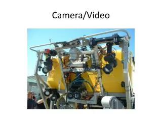
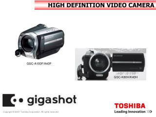
Video Camera • Sony XC-75 CCD Black and White Video Camera Module • We will have to determine from where in the camera we will get the shutter signal • The input to the camera will be the reflected light from the image
Block Diagram Timing signal and 250K clock Timing Circuitry DMX Interface Viewed image Intensity Adjustment Synchronized Signal Power Compensation Strobe Video Recorder Light input Light Sensor Image Reflected Light Video input (reflected light)
Timing Circuitry • Delay Circuitry to insure strobe fires during time when shutter is open. • This delay will be calculated and implemented with an RC circuit • 250 KHz clock signal • This will be used to shift the bits of data to the strobe at the necessary 250 Kbaud rate as specified by DMX • This will be implemented using a 555 timer
Block Diagram Timing signal and 250K clock Timing Circuitry DMX Interface Viewed image Intensity Adjustment Synchronized Signal Power Compensation Strobe Video Recorder Light input Light Sensor Image Reflected Light Video input (reflected light)
Sensor • We will be using a photodiode to sense the light output from the strobe • Circuit design for converting photodiode output to useable levels has yet to be explored
Block Diagram Timing signal and 250K clock Timing Circuitry DMX Interface Viewed image Intensity Adjustment Synchronized Signal Power Compensation Strobe Video Recorder Light input Light Sensor Image Reflected Light Video input (reflected light)
Power Compensation • Window Detector • This will determine the need to increase or decrease the intensity of the strobe • The measured value of intensity from the sensor is the input and will be compared to ideal intensity levels which will be determined experimentally • The output will be a signal denoting the need to increase or decrease the intensity
Block Diagram Timing signal and 250K clock Timing Circuitry DMX Interface Viewed image Intensity Adjustment Synchronized Signal Power Compensation Strobe Video Recorder Light input Light Sensor Image Reflected Light Video input (reflected light)
Strobe • Snapshot DMX/D • Requires differential input of DMX512 signal • Will operate in DMX mode where intensity is the first byte of data received, duration is second, and the rate is set by DMX refresh
Block Diagram Timing signal and 250K clock Timing Circuitry DMX Interface Viewed image Intensity Adjustment Synchronized Signal Power Compensation Strobe Video Recorder Light input Light Sensor Image Reflected Light Video input (reflected light)
DMX Interface • Increment or decrement strobe intensity based on output from power compensation circuitry. • Use preset duration value (found experimentally) to maximize strobe effectiveness. • Output appropriate DMX signals to strobe using 250Kbaud timing clock.
DMX Interface • The rate is determined by DMX refresh • The strobe will fire at the end of a packet of data • Sample packet of data Duration Data Break - 88us Intensity Data Mark after break - 8 us Idle line Stop Bits for data Start bit for data Start code - 44us
DMX Interface Power Compensation Output Stop Bits Duration Presets Intensity Counter Start Bits 64-bit Shift Register RS-485 Interface 64-bit Counter Differential DMX-512 output to strobe 250 KBaud clock
DMX Interface Power Compensation Output Stop Bits Duration Presets Intensity Counter Start Bits 64-bit Shift Register RS-485 Interface 64-bit Counter Differential DMX-512 output to strobe 250 KBaud clock
DMX Interface Power Compensation Output Stop Bits Duration Presets Intensity Counter Start Bits 64-bit Shift Register RS-485 Interface 64-bit Counter Differential DMX-512 output to strobe 250 KBaud clock
DMX Interface Power Compensation Output Stop Bits Duration Presets Intensity Counter Start Bits 64-bit Shift Register RS-485 Interface 64-bit Counter Differential DMX-512 output to strobe 250 KBaud clock
DMX Interface Power Compensation Output Stop Bits Duration Presets Intensity Counter Start Bits 64-bit Shift Register RS-485 Interface 64-bit Counter Differential DMX-512 output to strobe 250 KBaud clock
DMX Interface Power Compensation Output Stop Bits Duration Presets Intensity Counter Start Bits 64-bit Shift Register RS-485 Interface 64-bit Counter Differential DMX-512 output to strobe 250 KBaud clock
Tradeoffs • Large shift register and counter would be difficult to implement and control. • Microprocessor is capable of controlling timing of data as well as transmission of data. • Window detector output will interface directly with a microprocessor without A/D conversion, thus eliminating round off error. • Software will make the project easy for future students to modify or add features.
Microprocessor • Interrupt driven timing control of data to follow DMX 512 standards • Will output serial data to RS-485 interface as shift register would
Parts List • Strobe - Snap Shot DMX/D • Video Camera - Sony XC-75 (in stock) • RS-485 Interface - MAX1480C • Sensor - EG&G Vactec PhotoDiode (in stock) • EMAC Evaluation Board (in stock) • Sensor amplification-AD823 dual precision, 16MHz, operational amplifier. LM741 dual in-line operational amplifier. (in stock)
Schedule of Tasks • Finish project by Student Expo • Other than that, we’re not sure how long things will take.