Controlling Gates: Enabling and Disabling Circuits with Controlled Inverters
This article explores the functionality of enabling and disabling circuits using gates and controlled inverters. It highlights the dual purpose of enable/disable signals: to block or unblock data signals from propagation and to turn logical devices on or off. We analyze input combinations to determine activation states for various gates and address timing waveforms for a 2-to-1 line multiplexer. Additionally, we discuss the importance of mutually exclusive enabling regions to prevent signal interference among multiple input channels, ensuring reliable circuit operation.

Controlling Gates: Enabling and Disabling Circuits with Controlled Inverters
E N D
Presentation Transcript
Controlling Gates Enabling/Disabling Circuits & Controlled Inverters
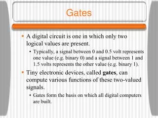
An enable/disable signal serves two basic purposes: 1) One is to block /unblock a data signal from further propagation. 2) The other one is to logically turn on/off logical devices (systems/subsystems)
What input combination of the enable signals will activate this gate?
{es2, es1, es0} = {1, 0, 1} {es3, es2, es1, es0} = {0, 1, 0, 1}
We may block a signal so that it does not subdue the other one
We may block a signal so that it does not subdue the other one
The enabling/disabling signals should be mutually exclusive. Why?
Setting en = e_ch0 = e_ch1’ will give us mutually exclusive signals