Enhancements in Upstream Polarimetry and Dispersion Analysis for April 2005 Meeting
This document outlines key discussions and updates from the April 6, 2005, IPBI meeting led by Ken Moffeit. Topics include effective shielding for the Cerenkov detector, improvements in extraction line optics, and the impact of dispersion on the upstream polarimeter. Detailed analyses address emittance growth versus dispersion levels, and the necessity for adequate space for laser beam insertion. Critical results reveal the limitations and challenges of the 20 mrad extraction line and strategies for optimizing Compton interaction points. Insights into surveying precision tolerances are also discussed.

Enhancements in Upstream Polarimetry and Dispersion Analysis for April 2005 Meeting
E N D
Presentation Transcript
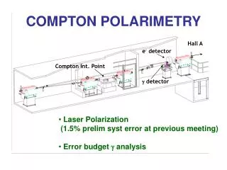
Polarimetry Design Updates IPBI Meeting 6 April 05 Ken Moffeit - Dispersion in upstream chicane - 20mrad extraction line 0.75 mrad beam stay clear location of Synchrotron Radiation Stripe Detector Comments about Shielding Number of Cells for Cerenkov Detector Better R22 etc - 2mrad extraction line R22 issues Energy and Polarimeter Chicanes - aligning the Compton IP Comments about surveying and tolerance for direction at Compton IPs. Ken Moffeit
Upstream Polarimeter with Dispersion = 5 mm Ken Moffeit
Upstream Polarimeter Emittance Growth versus Dispersion • Dispersion 5mm > 20mm • 2 is 16 times larger R(20mm) = R(5mm)/4 R3 (20mm)= R3 (5mm)/32 Emittance(20mm) = 45 Emit (5mm) Slide from Ray Arnold Ken Moffeit
Emittance Growth versus Dispersion Mark Woodley 30% For eta=20mm & 500 GeV beam: Short bend has pole-tip field of 5.4 kG; Long bend is half of that. Magnets ok for higher dispersion. 20% Horizontal Emittance Growth 10% 0 0 20 10 Chicane Dispersion (mm) Ken Moffeit
Upstream Polarimeter with dispersion = 10 mm Ken Moffeit
Space for Laser Beam Insertion/exit Only 1.4 meters between the inner dipoles is unacceptable. Peter Schuler needs a nominal 8 meters of space (or 14 meter between magnet centers) for the laser beam insertion/exit. This is to accomodate a crossing angle of 10 mrad, and keep the optics away from any synchrotron radiation. These conditions accomodate a vertical beam crossing, but retain a minimal magnet gap height of only 20 mm for all dipoles. Ken Moffeit
10 mm dispersion and 8m for laser input Ken Moffeit
20 mrad Extraction Line Eight Cerenkov Cells 1 cm wide Six cover the region between 36 GeV (12 cm from beam line) 25.1 GeV (17.8 cm) And 2 outside the kinematic limit Location of Synchrotron Detector Cerenkov Detector Shielding issues: Cells closest to beam pipe will see Synchrotron Radiation (below 10 MeV?) Ken Moffeit
LCWS Mar 05Yuri Nosochkov Improved R22 Optics Original Optics Good bad Ken Moffeit
Yuri Nosochkov (5 April 05) LCWS Improved R22 Optics Most Recent Optics Not Good > Lose 1cm at Cerenkov Det 1st Cell starts at 13 cm instead of 12 cm 2 mrad synchrotrotron swipe barely gets out of 0.75 mrad beam stay clear Good Ken Moffeit
2mrad extraction line R22 issues Energy and Polarimeter Chicanes Optics Improvement R22 ~ 1.3 now Need R22 ~ 0.5 Expand 2 mrad section to include Energy chicane Polarimeter chicane Ken Moffeit
Aligning the Compton IP Precision surveying should be good to <50 micro radians Can precision gyroscopes be used to achieve better accuracy? Perhaps <25 micro radians Ken Moffeit