Download
1 / 28
440 likes | 1.19k Vues
Liquid-Crystal Fabry -Perot filters. Wing-Kit Choi ( 蔡永傑 ) PKU-NTU Joint Workshop on Silicon Photonics, at Peking University 7/12/2013. Outline. Introduction to LC Introduction to PDLC/nano-PDLC Introduction to LCFP filters. Liquid Crystal (LC).

E N D
Liquid-Crystal Fabry-Perot filters Wing-Kit Choi (蔡永傑) PKU-NTU Joint Workshop on Silicon Photonics, at Peking University 7/12/2013
Outline • Introduction to LC • Introduction to PDLC/nano-PDLC • Introduction to LCFP filters
Liquid Crystal (LC) • A mainstream technology for today’s displays
Advantages of LC technology • Low voltage / low power consumption • Large electro-optic effects/Large birefringence • No moving part / Reliable • Long life • Robust • Compact • Easily scaled to large area / large number of pixels, etc
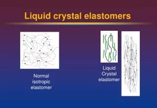
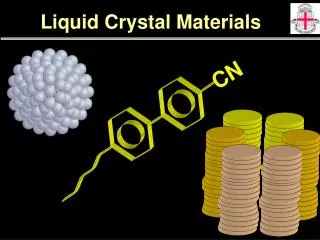
Liquid Crystal Crystalline Solid Amorphous Liquid temperature What are Liquid Crystals ? • Intermediate between crystalline solid and amorphous liquid • Usually found in organic molecules with: • Highly anisotropic shapes, e.g. rod or disc shape • Intermolecular forces: Crystals > Liquid crystals > Liquid
Amorphous Liquid Crystalline Solid Liquid Crystal • Highly ordered • Cannot flow • Optically anisotropic • Some degree of order • Can flow • Optically anisotropic • Highly disordered • Can flow easily • Optically isotropic Intermediate properties • Fluid propertiesof liquids + Optical propertiesof solids
Liquids Fluid properties Crystals Optical properties + Liquid Crystals Optical anisotropy + Molecules can be re-arranged easily by electric fields Large electro-optic effects are possible with only small applied voltages ! What so attractive about LCs ?
Slow response of LC (nematic) • Turn-ON is Fast (can be < 1ms) • Electric field driven • Turn-OFF is Slow (e.g. tens of ms) • Non-electric field driven • weak restoring force of LC molecules • A major limitation of LCs
How to achieve a faster LC response time ? • Use of different LC Phase • Modified Electrode Design • Different LC Mode • Polymer/LC e-o effects • Thinner cell gap • Over-Drive schemes • Dual frequency, etc
Introduction to PDLC • LC droplets dispersed in a solid polymer matrix • Most common method to produce PDLC: • Polymerization-Induced Phase Separation (PIPS) • Mix LC with monomers • Cure the mixture with UV light • Polymerization occurs • LC droplets form
Operation principle V > Vth V = 0 neff. > np neff. = np Scattering (Dark state) Transmission (Bright state)
Advantages • High Optical efficiency (No polarizers) • Ease of Fabrication (No Alignment layers) • Potentially Lower cost (No Alignment layers) • Compatible with plastic substrates to form Flexible Displays • Polarization Independent (in normal direction) • Fast Response time possible (esp. nano-PDLC)
Applications Electrically Switchable Windows • Other possible applications: • Variable Optical Attenuators (VOAs) • Project Displays • Reflective/ Flexible Displays • Tunable lens, etc
Transmission vs cell gap Thicker LC cell more scattering CR , V
Nano PDLC @ High Polymer concentration • ~ 50% polymer Max. scattering highest CR(droplet size ~ 1m ) • Polymer % , Scattering , CR (droplet size ) • Polymer > ~ 70%, ~ no scattering • (droplet size ~100nm) • Known as nano-PDLC 70% 60% 50%
Nano PDLC Fast Response (<1ms) possible • Polymer % , Response time (droplet size ) • Polymer interaction with LC stronger (more surface/volume ratio) • Polymer > ~ 70% (nano-PDLC), fast response < 1ms possible
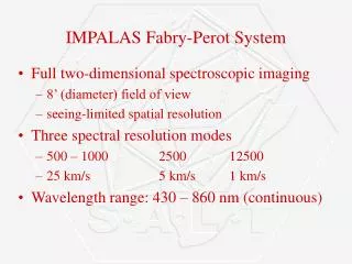
Fabry-Perot cavity Air ( or e.g. Liquid Crystal) Incident light T: transmittance R: reflectance n’ : the refractive index of the material d’ : the thickness of the etalon Transmitted light Highly reflective mirror (with glass substrate)
Wavelength tuning Tuning =~ 50nm
LCFP filters • First Proposed by a group at Rockwell Int. Science Centre, US, 1981 (Gunning et al) • To employ large n of LC: • Highly efficient wavelength tunable filters • Visible and Infrared Applications • Lower Voltage • Wider tuning range compared to other solid e-o materials
LCFP filters • Since 1990, further improved by groups at e.g. : 1) Bell Core , NJ ( Patel et al) 2) NTT Optoelectronics, Japan (Hirabayashi et al) for WDM in telecommunications • with Lower Loss, narrow bandwidth (<1-2nm), wide tunable range
LCFP (using PA-LC) Spectrum with Pol. And without Pol. Wavelength tuning ne no (Bellcore ,1990)
LCFP (Polarization Independent) Split into 2 components by Calcite Spectrumvs V without Pol. (Bellcore, 1991)
LCFP (Polarization Independent) Spectrum vs V without Pol. At > ~2.5V , ne and no modes merge (Bellcore,1991)
High speed LCFP using FLC • High speed (<100s) • Binary • Bistable (Bellcore,1993)
High speed LCFP using DHFLC • High speed (< ~ 100 s) • Low Voltage • May have hysteresis effect (Cambridge, 1996)
High speed LCFP using Sm*A LC • High speed (<10 s) • High Voltage • Elevated temp. • Tilted alignment (complicated) (Colorado, 1996)
Thank You!! Liquid Crystal Display & Photonics Laboratory Wing-Kit Choi (蔡永傑) National Taiwan University wkchoi@cc.ee.ntu.edu.tw Tel: +886-2-3366-3669