LIQUID CRYSTAL DISPLAY
LIQUID CRYSTAL DISPLAY. ~ By Ankit Goyal Ankit Goyal Anurag Chaurasia Himanshu Aggrawal Priya Ranjani Das B. Most used a cathode-ray tube as a display device in 20 century. CRT: Glass tube that is narrow at one end and opens to a flat screen at the other end.

LIQUID CRYSTAL DISPLAY
E N D
Presentation Transcript
LIQUID CRYSTAL DISPLAY ~ By Ankit Goyal Ankit Goyal AnuragChaurasia HimanshuAggrawal PriyaRanjani Das B
Most used a cathode-ray tube as a display device in 20 century. CRT: Glass tube that is narrow at one end and opens to a flat screen at the other end. Narrow end contains electron guns. Single gun for monochrome and three guns for color. Display screen is covered with tiny phosphor dots that emit light when struck by the electron gun. Traditional Displays
CRT Bulky, heavy, use vacuum tube technology. Using technology that was developed in the20thcentury. LCD LCD monitors are very popular due to low manufacturing costs. Light, sleek, energy-efficient, have sharp picture. From CRT to LCD
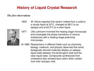
History of Displays • In1888 Friedrich Reinitzer discovers the liquid crystalline properties of cholesterol from carrots that is responsible for the generation of colors at the two melting points of the cholesterol. • In 1936 the Marconi Wireless Telegraph company places a patent on The Liquid Crystal Light Valve, which is the first practical application of Liquid Crystal technology. • In 1962 Richard Williams of the RCA discovered the electro-optic properties of liquid crystals. He found out that when an electrical current is sent through a thin layer of liquid crystals stripe-patterns form an optical effect of emitting various colors. This effect inside the liquid crystal is later called “Williams domains”.
Introduction to LCD • In a color LCD, each pixel is comprised of a red, green and blue sub pixel, each with its own color filter. • Colors are produced by applying a small voltage at each sub pixel to vary the intensity of red, green, or blue light to pass through it. This causes a color picture to be displayed on the LCD. • It does this independently for each of many tiny areas (pixels) on the screen. • An LCD controls light from a backlight or form surrounding : it does not emit light. • Sub pixels can change fast enough to allow moving pictures to be displayed. This changing rate is called refresh rate.
Colored Lcd • Each row of sub pixels has its own narrow color filter stripe - red, green and blue. • You can see these with a x30 magnifier on a laptop, or TV, LCD screen. • If all the sub pixels in an area are bright, then we see white there. If they are dark, we see black. • Sub pixels are too small to see individually by eye, so their colors mix . • We see colors that depend on the brightness's of adjacent R, G & B sub pixels. • Each LCD sub pixel is controlled by a voltage (applied using conductors you can see through) to create the right amounts of R, G & B for each part of the display.
GREEN BLUE RED RED+GREEN +BLUE BLUE+GREEN RED+BLUE RED+GREEN
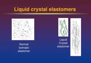
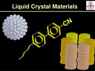
What is a liquid crystal?? • All materials are comprised of vast numbers of tiny particles (molecules) • It is basically another state of matter which behaves both as liquids and solids. • A liquid crystal has rod-like particles that all point in the same direction (more or less) • In an LCD, the thin layer of material used will remain a liquid crystal over a wide temperature range (typically from -20oC to +80oC) • Note that a liquid crystal is not solid, liquid or gas. It is an additional phase of matter. • It has unusual optical properties, but these can normally only be seen using Polarizer
Realization of a LCD • Light can be polarized. • Liquid crystals can transmit and polarize light. • The structure of liquid crystals can be changed by passing electrical current. • There are transparent materials that can conduct electricity.
Polarization • It is a property of transverse waves that describes the orientation of its oscillations. • In electromagnetic radiation (light) , it is specified by the orientation of the waves electric field. • Light generated by, say, a light bulb is a mixture of all the possible polarizations; we call such a light wave un-polarized. • Polaroid filters are capable of selecting a particular polarization state from an incident light wave. By convention the polarization of a light wave is specified by the orientation of the electric field.
What are polarizers • Polarizer are thin plastic sheets used for the lenses of Polaroid sunglasses • The sheet has a preferred direction (created by stretching it when it is made) • If two sheets have their preferred directions parallel, they will allow light to pass • If their preferred directions are crossed at a right angle, they will block light and look black, or dark blue • At 45 degrees, they look gray Parallel 45 degrees Crossed
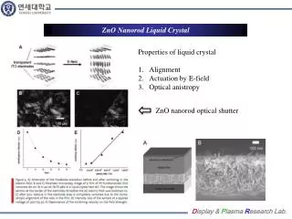
How a Polarizer is used? • An LC shutter between crossed polarizer “uncrosses” them and allows light to pass OFF Crossed LC Shutter
How a Polarizer is used? OFF Parallel LC Shutter An LC shutter between parallel polarisers “crosses” them and light is blocked
LC Shutter LC Shutter Crossed Parallel ON ON Figure 1 Figure 2 • An LC shutter placed between crossed polarisers on a light box allows light to pass. • If ~3Vac is applied to its conductors. The LCD becomes black. See Figure 1 • When the 3Vac is removed, the LCD becomes clear after a short delay. • If the polarisers are parallel the LCD goes from black to clear. See Figure 2
How liquid crystal Works in LCD? • In an LCD, it is used in a thin layer (~0.005 mm thick) between glass plates, when it appears transparent • Surface coatings on the plates make its rod-like particles twist by 90o through the layer • The LCD changes its optical properties when a small voltage is applied to clear conducting layers (made of Indium Tin Oxide, ITO), on the inside surface of each plate. This voltage is always AC, since DC voltage (e.g. from a battery) would damage the LCD. • Applying the voltage realigns the tiny particles perpendicular to the plates • The resulting optical change can only be seen using polarisers, as shown
Light Intensity Graph of Transmitted Light Intensity against Voltage applied to an LCD with Crossed Polarisers white Transmitted Light Intensity (Lux) black 0 1V 2V 3V Between 0V and 3Vac, a graph of the light intensity against voltage shows that grays are observed above ~ 1V threshold. LCD Voltage
Passive vs Active Matrix Passive -matrix addressed Active-matrix addressed Small monochrome displays such as those found in personal organizers, or older laptop screens have a passive-matrix structure Each row or column of the display has a single electrical circuit. The pixels are addressed one at a time by row and column addresses. The pixel must retain its state between refreshes without the benefit of a steady electrical charge. As the number of pixels (and, correspondingly, columns and rows) increases, this type of display becomes less feasible. High-resolution color displays such as modern LCD computer monitors and televisions use an active matrix structure. A matrix of thin-film transistors (TFTs) is added to the polarizing and color filters. Each pixel has its own dedicated transistor, allowing each column line to access one pixel. When a row line is activated, all of the column lines are connected to a row of pixels and the correct voltage is driven onto all of the column lines. The row line is then deactivated and the next row line is activated. Active-matrix addressed displays look "brighter" and "sharper" than passive-matrix addressed displays of the same size, and generally have quicker response times, producing much better images.
Passive–matrix V/S Active-matrix Passive -matrix addressed Active-matrix addressed
Active Matrix Technologies Twisted Nematic(TN) • Twisted nematic displays contain liquid crystal elements which twist and untwist at varying degrees to allow light to pass through. • When no voltage is applied to a TN liquid crystal cell, the light is polarized to pass through the cell. • In proportion to the voltage applied, the LC cells twist up to 90 degrees changing the polarization and blocking the light's path. • By properly adjusting the level of the voltage almost any grey level or transmission can be achieved.
In-plane switching (IPS) • In-plane switching is an LCD technology which aligns the liquid crystal cells in a horizontal direction. • In this method, the electrical field is applied through each end of the crystal, but this requires two transistors for each pixel instead of the single transistor needed for a standard thin-film transistor (TFT) display. • With older versions of IPS, before LG Enhanced IPS was introduced in 2009, the additional transistor resulted in blocking more transmission area, thus requiring a brighter backlight, which consumed more power, and made this type of display less desirable for notebook computers. • This technology can be found in the Apple iMac and iPad as well as the Hewlett-Packard EliteBook 8740w.
Advanced fringe field switching AFFS is developed by HYDIS TECHNOLOGIES CO.LTD, Korea (formally Hyundai Electronics, LCD Task Force). AFFS-applied notebook applications minimize color distortion while maintaining its superior wide viewing angle for a professional display. Color shift and deviation caused by light leakage is corrected by optimizing the white gamut which also enhances white/grey reproduction.
Vertical Alignment Vertical alignment displays are a form of LCDs in which the liquid crystal material naturally exists in a vertical state removing the need for extra transistors (as in IPS). When no voltage is applied, the liquid crystal cell remains perpendicular to the substrate creating a black display. When voltage is applied, the liquid crystal cells shift to a horizontal position, parallel to the substrate, allowing light to pass through and create a white display. VA liquid crystal displays provide some of the same advantages as IPS panels, particularly an improved viewing angle and improved black level.
Blue Phase Mode • Blue phase LCDs do not require a liquid crystal top layer. • Blue phase LCDs are relatively new to the market,and very expensive because of the low volume of production. • They provide a higher refresh rate than normal LCDs, but normal LCDs are still cheaper to make and actually provide better colors and a sharper image.
Advantages of LCD • Physical Size • Compact and Lightweight • Space saving • Can be mounted on a wall or panel • Display Size • Power Consumption and Radiation Emission • Consume less energy and more durable • Doest not emit Radiation • Not subject to Electromagnetic Interference • Viewing • Cause less eyestrain • Does not flicker or glare
Drawbacks • Although LCDs typically have more vibrant images and better "real-world" contrast ratios (the ability to maintain contrast and variation of color in bright environments) than CRTs, they do have lower contrast ratios than CRTs in terms of how deep their blacks are. • LCDs typically have longer response times than their plasma and CRT counterparts. • LCDs appear to exhibit motion blur as the human eye follows moving objects, where some CRT screens do not. • LCD panels using TN tend to have a limited viewing angle relative to CRT and plasma displays. • Consumer LCD monitors tend to be more fragile than their CRT counterparts. • Dead pixels can occur when the screen is damaged or pressure is put upon the screen. • The cold cathode fluorescent lamps typically used for back-lights in LCD screens contain mercury, a toxic substance, though LED-backlit LCD screens are mercury-free. • Pattern based flicker, caused by imperfect voltage balance.
Super-twisted nematic LCDs • Twisted nematic displays rotate the director of the liquid crystal by 90 degrees , but super-twisted nematic displays employ up to a 270 degrees rotation. This extra rotation gives the crystal a much steeper voltage-brightness response curve and also widens the angle at which the display can be viewed before losing much contrast. • With the sharper response, it is possible to achieve higher contrast with the same voltage selection ratio. Therefore, the degree to which multiplexing is possible is greatly increased. The largest common super-twist displays have up to 500 rows.
Surface-Stabilized Ferroelectric LCDs • The surface-stabilized ferroelectric liquid crystal display shows great promise. It uses chiralsmectic liquid crystal---a type in which the director rotates around a cone of directions 22.5 degrees from the perpendicular of the layers. The hope is to make the film so thin that the director will not rotate. The planar layers are perpendicular to the glass plates of the display. • Surface-stabilized ferroelectric displays have the distinct advantage that switching speeds are very high since electric field is necessary for both turning a pixel on and for turning it off.
3D LCD • Hitachi working on glasses-less 3D LCD • Last year at CEATEC Hitachi showed off a 10-inch prototype with a VGA screen, which used 16 projectors to create the glasses-less 3D, which is visible dependent on the viewing angle. • Glasses would prove the barrier for most people considering buying a 3DTV, but it’s not yet known whether the parallax barrier technology can actually compete with what we’ve seen from Panasonic, who’s the only manufacturer with a 3D plasma out.