LCD Panels: Basic Components, Operation, and Types
340 likes | 413 Vues
Learn about the layers in an LCD panel, how polarization works, and the process of light passage through the panel. Explore the different types of LCD panels, their driving mechanisms, and the alignment of liquid crystal molecules.

LCD Panels: Basic Components, Operation, and Types
E N D
Presentation Transcript
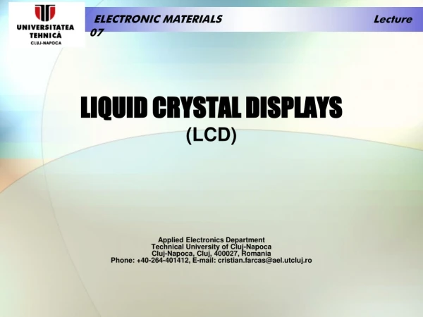
ELECTRONIC MATERIALS Lecture 07 LIQUID CRYSTAL DISPLAYS(LCD) Applied Electronics DepartmentTechnical University of Cluj-NapocaCluj-Napoca, Cluj, 400027, RomaniaPhone: +40-264-401412, E-mail: cristian.farcas@ael.utcluj.ro
ELECTRONIC MATERIALS Lecture 07 • What are the basic components in an LCD panel? • How does an LCD work? • What are the different types of LCD panels? • How are LCD panels driven?
ELECTRONIC MATERIALS Lecture 07 WHAT ARE THE BASIC COMPONENTS IN AN LCD PANEL? An LCD panel, or more commonly known as a piece of “glass”, is constructed of many layers. Figure shows all the layers that are typically present in LCD panels. The first layer is called the front polarizer. Basic LCD components
ELECTRONIC MATERIALS Lecture 07 Polarization is a process or state in which rays of light exhibit different properties in different directions, especially the state in which all the vibration takes place in one plane. Essentially, a polarizer passes light only in one plane. As shown in figure, if light is polarized in one plane, by passing through a polarizer, it cannot pass through a second polarizer if its plane is 90° out of phase to the first. The front polarizer is applied to the outside surface of the top piece of glass. The top piece of glass also provides structural support for the LCD panel. On the bottom of the top glass, a transparent coating of Indium-Tin Oxide* (ITO) is applied to the glass. ITO is conductive and forms the backplaneor common electrodes of the LCD panel. The patterns of the backplane and segment ITO forms the numbers, letters, symbols, icons, etc. Polarizers out of phase
ELECTRONIC MATERIALS Lecture 07 After the ITO has been applied to the glass, a thin polyimide coating is applied to the ITO. The polyimide is “rubbed” in a single direction that matches the polarization plane of the front polarizer. The action of “rubbing” the polyimide causes the Liquid Crystal (LC) molecules in the outermost plane to align themselves in the same direction. The next layer is a reservoir of LC. The LC fluidhas many planes of molecules. The next layer is the polyimide coating on the bottom glass followed by the ITO segment electrodes. The bottom glass also supplies structural integrity for the LCD panel as well as mounting surface for the electrode connections. Applied to the external surface of the bottom glass is the rear polarizer. Depending on the type of viewing mode employed by the LCD panel, the axis of polarization is the same or 90° apart from the front polarizer. *Indium tin oxide (ITO, or tin-doped indium oxide) is a mixture of indium(III) oxide (In2O3) and tin(IV) oxide (SnO2), typically 90% In2O3, 10% SnO2 by weight. It is transparent and colorless in thin layers.
ELECTRONIC MATERIALS Lecture 07 LC molecules are long and cylindrical. On any plane within the LC fluid, the molecules align themselves such that the major axis of each molecule is parallel to all others, as shown in figure. The outermost planes of LC molecules will align themselves on the same axis that the polyimide is “rubbed”. The direction of “rubbing” of the polyimide on the bottom glass is 90° apart from that of the polyimide on the top glass. This orientation creates the twist in the LC fluid. LC molecules in alignment
ELECTRONIC MATERIALS Lecture 07 A consequence of this alignment is that each intermediate plane of LC molecules will have a slightly different orientation from the plane above or below as seen in figure. The twisting of the planes causes the polarization of the light to twist as it passes through the LC fluid. The twisting of the LC planes is critical to the operation of the LCD panel. LC molecules plane orientation
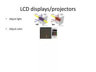
ELECTRONIC MATERIALS Lecture 07 HOW DOES AN LCD WORK? Figure shows how an LCD panel creates a pixel that is OFF. For this example the LC fluid is not energized, i.e. there is 0VRMS potential between the backplane and segment electrodes. Path of light for OFF pixel (positive image)
ELECTRONIC MATERIALS Lecture 07 The following is a step-by-step description of the path light takes through the LCD panel: 1. Light enters the panel through the rear polarizer. At this point the light becomes polarized to the vertical plane. 2. The polarized light passes unobstructed through the transparent backplane electrode. 3. As the polarized light passes through the LC fluid it gets twisted into the horizontal plane. 4. The polarized light passes unobstructed through the transparent segment electrode. 5. Since the light is now polarized in the horizontal plane, it passes unobstructed through the front polarizer which has a horizontal polarization. 6. The observer does not detect that the pixel is on because the light has not been obstructed.
ELECTRONIC MATERIALS Lecture 07 If a potential is applied across the backplane and segment electrodes, the LC fluid becomes energized. The LC molecule planes will now align themselves such that they are parallel to the electrical field generated by the potential difference. This removes the twisting effect of the LC fluid. Next figure shows a pixel that is ON or, more specifically energized. Path of light for ON pixel (positive image)
ELECTRONIC MATERIALS Lecture 07 The following is a step-by-step description of the path that the light takes through this LCD panel. 1. Light enters the panel through the rear polarizer. At this point the light becomes polarized to the vertical plane. 2. The polarized light passes unobstructed through the transparent backplane electrode. 3. As the polarized light passes through the LC fluid it does not twist and remains in the vertical plane. 4. The polarized light passes unobstructed through the transparent segment electrode. 5. Since the light is still polarized in the vertical plane, it is obstructed by the front polarizer which has a horizontal polarization. 6. The observer detects that the pixel is on because the light has been obstructed and creates a dark image on the panel.
ELECTRONIC MATERIALS Lecture 07 LCD IMAGES LCDs have the capability to produce both positive and negative images. A positive imageis defined to be a dark image on a light background. In a positive image display, the front and rear polarizers are perpendicular to each other. Unenergized pixels and the background area transmit the light and energized pixels obstruct the light creating dark images on the light background. A negative imageis a light image on a dark background. In this type of display, the front and rear polarizers are aligned to each other. Unenergized pixels and the background inhibit light from passing through the display. Energized pixels allow the light to pass creating a light image on a dark background. There are essentially three types of viewing modes for a LCD: reflective, transmissive, and transflective. Typically reflective displaysuse only positive images. The front and rear polarizers are perpendicular to each other. The LCD panel will have an additional layer added to the bottom of the display, a reflector. The next figure shows the diagrams for pixels that are ON and OFF for reflective displays. Here again, the path that light takes is described in a step-by-step fashion for a pixel that is OFF in a positive image display.
ELECTRONIC MATERIALS Lecture 07 Reflective LCD path of light (OFF pixel)
ELECTRONIC MATERIALS Lecture 07 1. Light enters the panel through the front polarizer. At this point the light becomes polarized to the vertical plane. 2. The polarized light passes unobstructed through the transparent backplane electrode. 3. As the polarized light passes through the LC fluid it gets twisted into the horizontal plane. 4. The polarized light passes unobstructed through the transparent segment electrode. 5. Since the light is now polarized in the horizontal plane, it passes unobstructed through the rear polarizer which has a horizontal polarization. 6. The reflector behind the rear polarizer reflects the incoming light back on the same path. 7. The observer does not detect that the pixel is ON because the light was reflected back. A pixel that is ON follows the same basic steps except that the light never reaches the reflector and therefore does not return to the observer. Reflective displays lend themselves to battery powered applications because the images are created using ambient light sources. These displays are very bright under proper lighting conditions, with excellent contrast, and have a wide viewing angle.
ELECTRONIC MATERIALS Lecture 07 Reflective LCD path of light (ON pixel)
ELECTRONIC MATERIALS Lecture 08 Transmissive displaysdo not reflect light back to the observer. Instead, they rely upon a light source behind the panel to create images. A transmissive display has front and rear polarizers that are in phase to each other. Next figures shows the OFF and ON diagrams for a transmissive display. The path of light is described below for the ON state only in a positive image display. ON Transmissive LCD path of light (ON pixel) – negative image
ELECTRONIC MATERIALS Lecture 08 OFF Transmissive LCD path of light (OFF pixel) – negative image
ELECTRONIC MATERIALS Lecture 08 1. Light enters the panel through the rear polarizer. At this point the light becomes polarized to the vertical plane. 2. The polarized light passes unobstructed through the transparent segment electrode. 3. As the polarized light passes through the LC fluid it gets twisted into the horizontal plane. 4. The polarized light passes unobstructed through the transparent backplane electrode. 5. Since the light is now polarized in the horizontal plane, it is obstructed by the front polarizer which has a vertical polarization. Very little light passes through the front polarizer. 6. The observer does not detect that the pixel is ON because the light was obstructed. An OFF pixel would allow the light to pass through the display unobstructed because the polarization does not get twisted by the LC fluid. These displays are very good for very low light level conditions. They are very poor when used in direct sunlight because the sunlight swamps out the backlighting.
ELECTRONIC MATERIALS Lecture 08 The third type of display is called transflective. As you can probably tell from the name, it is a combination of reflective and transmissive. A white or silver translucent material is applied to the rear of the display. It reflects some of the ambient light back to the observer while also allowing backlighting. Transflective displays are very good for applications which have varying light conditions such as gas pumps. They must operate during the day in bright sunlight, but must also operate at night. Transflective displays have lower contrast ratios than reflective displays because some of the light passes through the reflector.
ELECTRONIC MATERIALS Lecture 08
ELECTRONIC MATERIALS Lecture 08 DRIVER VOLTAGES The number one cause of LCD damage is having a DC voltage applied to it. A DC voltage will deteriorate the LC fluid such that it cannot be energized. The LCD driver waveforms are designed to create a 0VDC potential across all pixels. The specifications for a LCD panel will include some RMS voltages such as VOFF and VON. A third voltage is VTH which is the RMS voltage across an LCD pixel when contrast reaches a 10% level. Often this voltage is used as VOFF. VON is defined as the RMS voltage applied by the LCD driver to the segment electrode that creates an ON pixel which is typically at the 90% contrast level. It is desirable that VON be much greater than VOFF. The figure graphically represents the voltage potential versus the contrast across a pixel. The final specification for an LCD panel is the discrimination ratio which is VON divided by VOFF (VON/VOFF). The discrimination ratio specifies what type of contrast levels the LCD panel will be able to achieve.
ELECTRONIC MATERIALS Lecture 08 BACKLIGHTING A variety of methods exist for backlighting LCD panels, such as, incandescent lamps, LEDs, and electroluminescent lamps. Incandescent lamps require some type of reflector to provide uniform lighting to all areas of the panel. LEDs require some type of lightguide or lightpipe to evenly distribute light. Electroluminescent lamps typically come in some type of a panel arrangement. Other lighting methods are available for specific applications, such as fluorescent. Table 2 provides a comparison of these methods of backlighting.
ELECTRONIC MATERIALS Lecture 08
ELECTRONIC MATERIALS Lecture 08 CONNECTION METHODS The first method of connecting the LCD panel to the world was the dual-in-line pin (as in figure). These pins provide excellent protection for harsh environments, vibration or shock. The LCD panel is either soldered directly to the printed circuit board (PCB) or inserted into headers. DUAL IN-LINE PINS
ELECTRONIC MATERIALS Lecture 08 The second method is elastomeric connectors. This method allows fast assembly/disassembly without having to solder the LCD panel. Elastomeric connectors are used on small applications where space is a concern. These connectors are relatively resistant to shock and vibration, but special consideration must be used when the panel will be exposed to harsh environments. ELASTOMERIC CONNECTORS
ELECTRONIC MATERIALS Lecture 08 One of the newer methods is the flex connector. A PCB and the LCD panel are connected by a flexible cable using a heat seal process. The flexible cable is typically a anisotropic connective film that is applied to the PCB and LCD panel using heat and pressure. These connectors were designed for harsh environments where the connector must be flexible enough to prevent breakage during stress. These connectors are becoming more popular with large or remotely mounted LCD panels. FLEX CONNECTORS
ELECTRONIC MATERIALS Lecture 08 WHAT ARE THE DIFFERENT TYPES OF LCD PANELS? LCD panels come in many flavors depending on the application and the operating environment. LCDs can be classified in two ways. First of all, LCDs come in direct drive or multiplex drive variations. Direct drive, otherwise known as static, means that each pixel of the LCD panel has an independent driver. The LCD panel also has only one backplane. A static drive panel also has static bias. Bias is defined as the number of voltage levels the LCD driver uses to create images on the screen. The number of voltage levels is equivalent to the 1 + 1/bias. Static bias refers to two voltage levels which create a square wave, ground and VDD. Static drive panels also have the best contrast ratios over the widest temperature range. Multiplex drive panels reduce the overall amount of interconnections between the LCD and the driver. Put simply, multiplex panels have more than one backplane. A multiplex LCD driver produces an amplitude-varying, time synchronized waveform for both the segment and backplanes. These waveforms allow access to one pixel on each of the backplanes. This significantly increases the complexity of the driver. The number of backplanes a panel has is referred to the multiplexing ratio or “MUX” of the panel. MUX also refers to duty cycle. For instance, a 1/3 MUX panel has three backplanes. The bias for multiplex panels is at least 1/2 - 1/5 for segment type drivers and from 1/8 - 1/33 for dot matrix. Table 3 illustrates the advantage of multiplex panels.
ELECTRONIC MATERIALS Lecture 08
ELECTRONIC MATERIALS Lecture 08 The other method of classifying LCD panels is the type of display notation used, i.e. segment, dot matrix, or functional. Segment displays are usually the 7-segment, 14-segment, or 16-segment (“British Flag”) types used to create numbers and letters. These type of displays are static drive which provides the best contrast and readability in sunlight.
ELECTRONIC MATERIALS Lecture 08 Dot matrix displays are always multiplex type displays due to the large number of pixels required and pin limitations on the driver. Dot matrix displays can create more natural letters and numbers as well as custom graphic symbols. The third type of display is most commonly used in conjunction with the previous types. A function indicator or icon provides status information about the system. They are only capable of being turned on or off. One example would be a digital multimeter. The meter has three 1/2 digits which are 7-segment type and also some icons for volts, amps, ohms and the ranges for μ, m, K, and M.
ELECTRONIC MATERIALS Lecture 08 An earlier we mentioned that a LCD driver must maintain a 0VDC potential across each pixel. The voltage applied across a particular pixel is the voltage on the COM pin minus the voltage on the SEG pin. If the resulting voltage is at or above the VON threshold then the pixel is visible. Otherwise the voltage will be at or below the VOFF threshold and the pixel will not be visible. This formula is used for all drive methods. STATIC WAVEFORMS
ELECTRONIC MATERIALS Lecture 06 Indium tin oxide (ITO) Indium tin oxide (ITO, or tin-doped indium oxide) is a solid solution of indium(III) oxide (In2O3) and tin(IV) oxide (SnO2), typically 90% In2O3, 10% SnO2 by weight. It is transparent and colorless in thin layers. In bulk form, it is yellowish to grey. In the infrared region of the spectrum it is a metal-like mirror. Indium tin oxide's main feature is the combination of electrical conductivity and optical transparency. However, a compromise has to be reached during film deposition, as high concentration of charge carriers will increase the material's conductivity, but decrease its transparency. Thin films of indium tin oxide are most commonly deposited on surfaces by electron beam evaporation, physical vapor deposition, or a range of sputter deposition techniques.
ELECTRONIC MATERIALS Lecture 06 ITO is mainly used to make transparent conductive coatings for liquid crystal displays, flat panel displays, plasma displays, touch panels, electronic ink applications, organic light-emitting diodes, solar cells,antistatic coatings and EMI shieldings. In organic light-emitting diodes (OLED), ITO is used as the anode (hole injection layer). ITO has been used as a conductive material in the plastic electroluminescent lamp of toy Star Wars type lightsabers. ITO is also used for various optical coatings, most notably infrared-reflecting coatings (hot mirrors) for architectural, automotive, and sodium vapor lamp glasses. Other uses include gas sensors, antireflection coatings, electrowetting on dielectrics, and Bragg reflectors for VCSEL lasers.