Multi-Bit Differential Signaling Prototype Chip
This prototype chip developed by students at the University of Pittsburgh showcases Multi-Bit Differential Signaling (MBDS) as an innovative alternative to Low Voltage Differential Signaling (LVDS). Utilizing efficient channel encoding, the MBDS system features N-choose-M encoding, offering noise rejection equivalent to LVDS while reducing pad count and power consumption. The demonstrator chip operates with various driver and receiver widths and includes thorough testing for compatibility with LVDS standards. This work presents a significant advancement in high-capacity data transmission technologies.

Multi-Bit Differential Signaling Prototype Chip
E N D
Presentation Transcript
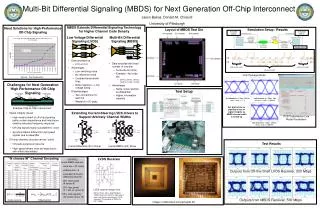
Multi-Bit Differential Signaling Prototype Chip Student Designers: Jason D. Bakos, Leo Selavo, Amit Gupta Faculty Advisor: Donald M. Chiarulli University of Pittsburgh
Multi-Bit Differential Signaling (MBDS) • Alternative to Low Voltage Differential Signaling (LVDS) Code set size Effective bits • Uses channel encoding • Data encoded with fixed number of 1’s • N-choose-M (nCm) encoding • Example 4c2 code set: {0011}, {0101}, {0110}, {1001}, {1010}, {1100} • Advantages • Equivalent noise rejection to LVDS • Low switching noise • No reference noise • Coupled transmission lines • Low voltage swing • Higher information capacity than LVDS • EXAMPLE: 6c3 MBDS channel • Equivalent to 8-wire LVDS • 25% fewer pads (8 vs. 6 pads) • 25% less power (4 vs. 3 1-bits) • 125% code capacity (20 codes versus 16) IBM 5HP
Simulation Setup / Results • Demonstrator chip includes: • MBDS drivers with widths: 2, 4, 6, 8 • MBDS receivers with widths: 2, 4, 6, 8 Wire bond/solder balls models Extracted layout Signals sampled here 8” coupled striplines Extracted layout 4c2 channel at 1 Gbps, 500 bit times, scale +/- 600mV 2c1 channel at 1 Gbps, 500 bit times, scale +/- 1 V 8c4 channel at 1 Gbps, 500 bit times, scale +/- 600mV
Chip Testing Termination network at receivers 200 Mbps output with Quad-LVDS Receiver 500 Mbps with Custom LVDS Receivers • Experiment 1: • Outputs from off-the-shelf LVDS receiver • Compatibility with LVDS standard • Experiment 2: • Outputs from LVDS receivers on chip