Download
1 / 21
210 likes | 227 Vues
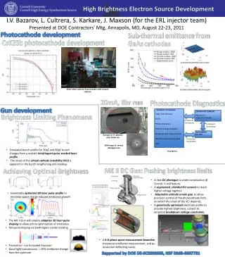
Diagnostic of Ultra High Brightness Electron Beams. Mikhail Krasilnikov (DESY) for the PITZ Team. Content: High brightness electron beam diagnostic overview longitudinal transverse slice Photo Injector Test facility at DESY in Zeuthen (PITZ) setup electron beam diagnostic at PITZ

E N D
Diagnostic of Ultra High Brightness Electron Beams Mikhail Krasilnikov (DESY) for the PITZ Team • Content: • High brightness electron beam diagnostic overview • longitudinal • transverse • slice • Photo Injector Test facility at DESY in Zeuthen (PITZ) • setup • electron beam diagnostic at PITZ • Emittance measurements at PITZ • single slit scan technique • recent results • Summary Ultra Bright Electron Sources Workshop, 29 June – 1 July 2011 The Cockcroft Institute, Daresbury
Diagnostic of High Brightness Electron Beams HB E-beam diagnostic • General: • bunch charge FC, ICT, Toroids • transverse position BPM: button, stripline, cavity • arrival time (phase) BAM, RF pickups Projected Slice Longitudinal (temporal) Transverse Energy distribution Current profile Transverse profile • Challenges • high charge / charge density • small beam dimensions (100…50um nm!) • high repetition rate • all the intercepting devices are damaged by measured beams • beam halo measurements Slice energy spread Long. phase space Proj.emittance, transv. phase space Slice emittance
Longitudinal Parameters Measurements • Temporal beam profile (bunch length) r(t) Frequency Domain Optical and laser techniques Time Domain Coherent radiations + Interferometer Electro Optical Sampling = EOS RF deflector Radiator + Streak-camera • Non intercepting and not disturbing • Based on optical properties of a non-linear crystal interacting with Coulomb field of e-beam Transition = CTR Diffraction = CDR • Intercepting diagnostic • Radiators • OTR (Al foil) • Cherenkov (aerogel) • Streak camera • T-resolution limited to 200...300 fs • Rather expensive • Light collection \transport dispersion free beam line is needed (reflective optic instead of lens) Synchrotron CSR Laser Wire Smith-Parcell • Non intercepting and not disturbing • Multi shot • Complicated setup Cherenkov • Interferometers (Michelson; Martin-Puplett) • Spectrum acceptance is restricted can impact the reconstructed beam profile • Guess distribution is needed
Longitudinal Parameters Measurements: RFD (TD) Map time (longitudinal) axis onto transverse coordinate • RFD: • Self calibration (cavity phasing) • Single shot • Intercepting diagnostic • Resolution down to tens of fs (f, V, str) • small transverse beam size and large beta function • uncorrelated transverse energy spread • induced slice energy spread • phase jitter of the beam w.r.t. RFD OTR beam images in the LCLS injector at 135MeV for a 800um long bunch with the deflecting cavity off (left) and on at 1MV (right). H. Loos, “Longitudinal diagnostics for short electron beam bunches”, SLAC-PUB-14120
Longitudinal phase space measurements • Spectrometer dipole ┴ RFD (Energy scale from beam in spectrometer, time scale with transverse deflector) Imaging of longitudinal phase space with RF deflector SPARC: 145MeV LCLS: 135 MeV t E Fast single shot measurements
Transverse Parameters Measurements Usually the largest error in transverse parameters measurements is coming from transverse profile and rms size determination • OTR monitors (~um Al foil) • High energy (>tens of MeV) • No saturation • Resolution limit closed to optical diffraction limit (~10um) • COTR effects (especially for compressed bunches) • Scintillator screens (e.g. YAG:CE, 100um) • High photon yield • Resolution grain dimensions (~50um?) (powder / thin crystal) • Saturation (0.04pC/um^2?) • Wire Scanner (good agreement with YAG measurements!) • Almost non-invasive • Higher beam power • Multi-shot measurements • 1D • Rather complicated setup, long measurement time • IPM (residual gas monitor) • CVD (diamond screen) long pulse train • “Indirect” (SR – Optical Synchrotron Interferometry, Scattering, ODR, etc) • Read out: • Zoom optics • CCD camera • 12bit • l~ 1um..400nm • controllable iris • Insertable filters
Transverse Phase Space (Emittance) Measurements Emittance dominated Space charge dominated • Multi screen: • Based on linear beam matrix approach • 3 beam size measurements (at 3 positions) are needed for the known elements of the transport matrix (phase advance) • Quad(s) scan • Beam size measurements as a function of varied transport matrix • Tomography • Related to Radon theorem: N-dim object reconstruction from M projections in (N-1) dim space • Slit mask techniques: • based on conversion of a space charge dominated beam into emittance dominated beamlets • Systematic error from quad strength determination(e.g hysteresis) • Thin lens model is not adequate • Large energy spread chromatic effects • Phase space distribution assumed to be homogeneous CSR (undulator) based?
Slit technique - general Emittance dominated beamlets • Multi slit mask = single shot measurement, but: • Overlapping of beamlets when optimized for high resolution • Low sampling of the phase space Space charge dominated beam Transverse phase space reconstruction • Slit mask: • Opening: small enough (scem) • Thickness: thick enough to scatter beam, but alignment / angle acceptance • Distance L: • Long enough divergence resolution • Not too long signal-to-noise L SPARC e-meter = phase space measurements along the beam line
Position of reconstruction RFD 12.28 14.56 13.8 13.04 15.32 z Phase Space Tomography (e.g. at PITZ) • The most used technique quadrupole(s) scan, but it yields only Twiss parameters and emittance, not the phase space. Thereforephase space tomography • Back projection • Filtered Back projection • Algebraic reconstruction technique (ART) • Maximum entropy (MENT) Courtesy G.Asova (PITZ)
Slice parameters measurements • Slice emittance: • RFD + Quad(s) scan • Acc off-crest + dipole • Slice energy spread • RFD + dipole P. Emma, A. Brachmann, D. Dowell, et al., SLAC, “Beam Brightness Measurements in the LCLS Injector”, Compact X-Ray FELs using High-Brightness Beams, 5-6.08.2010, LBNL 1 3 2
Photo Injector Test facility at DESY in Zeuthen • The Photo Injector Test facility at DESY in Zeuthen (PITZ) focuses on the development, test and optimization of high brightness electron sources for superconducting linac driven FELs: • test-bed for FEL injectors: FLASH, the European XFEL • small transverse emittance (~1 mm mrad @ 1 nC) • stable production of short bunches with small energy spread • further studies: dark current, QE,thermal emittance, … • + detailed comparison with simulations = benchmarking of photo injector physics • extensive R&D on photo injectors and test of new developments (laser, cathodes, beam diagnostics)
XFEL Photo Injector Key Parameters to be tested at PITZ 20ps Main efforts at PITZ towards XFEL photo injector
Beam diagnostics at PITZ Diagnostics for Transverse phase space andLongitudinal phase space <7 MeV <25 MeV
Slit scan technique at PITZ: evolution • ~2002-2003 rough divergence estimation using center beamlet, 8 bit camera • 2003-2005 sheared emittance estimation using 3 slit positions (0; +/-0.7*sigmaX), 8-bit camera • 2005-2008 – standard “manual” slit scan (~200um step) phase space reconstruction, 12-bit camera • 2009-2011 – automated synchronized slit scan with adjustable scan speed phase space “on-line”, 12-bit cameras, zoom option, scale procedure • The emittance measurement procedure at PITZ: • under permanent improvement in terms of resolution and sensitivity • as conservative as possible (100% rms emittance)! • !NB: measured emittance numbers are permanently reducing as a result of machine upgrades and extensive optimization of beam parameters “we are measuring more and more of less and less…”
2.64 m Observation screen EMSY1 (z = 5.74 m) Transverse projected emittance measurements at PITZ beam at EMSY screen transverse phase space Single slit scan technique • Emittance Measurement SYstem (EMSY) consists of horizontal / vertical actuators with • YAG / OTR screens • 10 / 50 m slits • Beam size is measured @ slit position using screen • Beam local divergence is estimated from beamlet sizes @ observation screen • 12-bit camera, quality criteria: max bit>3000 (from 4095=2^12-1); adjustment = gain X NoP • Image filtering (3sigma, bkg, x-ray, MOI) 2D scaled normalized RMS emittance scale factor ( >1 ) introduced to correct for low intensity losses from beamlet measurements x - RMS beam size measured with YAG screen at slit location SQRT(<x2>)- RMS beam size at slit location estimated from slit positions and beamlet intensities “100% RMS emittance” Statistics over all pixels in all beamlets pixel intensity
Slit scan technique at PITZ: how it works now • Setup the machine • laser temporal and transverse • laser BBA at the cathode • gun phase • bunch charge • booster phase and gradient – beam energy (longitudinal momentum) • For a chosen main solenoid current (bucking in compensation) • Beam transverse distribution (rms size) at EMSY 12-bit camera!; frames=50xSignal+50xBkg (laser shutter closed) with adjusted camera gain G and NoP • Beam transverse distribution at beamlet collection screen for MOI 12-bit camera! frames=50xSignal+50xBkg (laser shutter closed) with adjusted camera gain G and NoP • Slit scan (typical speed 0.1-0.5mm/sec) with simultaneous beamlet image taking. Synchronization of the slit position and the frame acquisition (10Hz!) with adjusted camera gain G and NoP • Slit scan with closed laser shutter for the average bkg calculation • Transverse phase space reconstruction and emittance calculations • Phase space linear shift to take the slit position into account • Scale procedure • Error analysis (systematic and statistics – e.g. 3x5)
Emittance measurements at PITZ (typical solenoid scan) Machine setup (07.05.2011M): BSA=1.2mm; gun=6deg off crest; 1nC; booster=on-crest preliminary Beam momentum after the gun Laser temporal profile Bunch charge tuning Beam momentum after the booster Laser transverse distribution
Emittance measurements at PITZ: typical solenoid scan 1) Solenoid scan for X and Y emittance 2) 3x3 statistics for the bes solenoid current preliminary beam at EMSY: 3x1 XPx: 3x3 YPy: 3x3 07.05.2011M: 3x3 stat: Xemit=(0.742±0.021stat) mm mradYemit=(0.782 ±0.028stat) mm mradXYemit=(0.761± 0.017stat) mm mrad 07.05.2011M: sol.scan: Xemit | Yemit | XYemit 0.778 | 0.701 | 0.738 Geometrical averaged emittance:
beam dump DISP3.Scr2 electron beam DISP3.Scr1 PITZ setup: now and upgrades during this year <7 MeV <25 MeV • HEDA2 • together with TDS: measure slice momentum spread down to 1 keV/c • Transverse Deflecting Structure (TDS) • time resolved measurements
Summary • High brightness electron beams require particular diagnostic for longitudinal and transverse phase space characterization: • Strong energy dependency (YAG for low energies, OTR – for high energies) • Non-invasive techniques are highly desirable • Slice parameters measurements are important • The main focus at PITZ small emittance electron beams. To reach this: • high gun gradients • cathode laser transverse and temporal shaping • machine stability • extensive machine optimization • Emittance measurement procedure • nominal method single slit scan • as conservative as possible 100% rms emittance • continuous improvement of the procedure • PITZ sets a benchmark for ultra high brightness electron sources: • specs for the European XFEL have been met (emittance <0.9 mm mrad at 1nC) and even surpassed • beam emittance has also been optimized for a wide range of bunch charges (20pc…2nC) • rather high duty factor (average power, long pulse trains) in stable operation
References General measurements of brightness and emittance C. Lejeune and J. Aubert, “Emittance and Brightness, definitions and measurements”, Adv. Electron. Electron Phys.,Suppl. A 13, 159 (1980). O. R. Sander, “Transverse Emiitance: Its Definition, Applications, and Measurements” in “Accelerator Instrumentation”, E. R. Beadle and V. J. Castillo, edts., (AIP CP212, 1991) pp. 127-155. R. Becker and W. B. Herrmannsfeldt, “Why pi and why mrad”, Rev. Sci. Instrum. 77(2006). A. Wu Chao, M. Tigner “Handbook of Accelerator Handbook of Accelerator Physics and Engineering Physics and Engineering” World Scientific C. A. Brau “What Brightness means” in The Physics and Applications of High Brightness Electron Beam”, World Scientific, p.20 M. Reiser, “Theory and design of charged particle beams”, Wiley‐VCH Shyh‐Yuan Lee, “Accelerator Physics”, World Scientific J. Clarke “The Science and Technology of Undulators and Wiggles” Oxford Science Publications H. Loos, “Diagnostic Systems for High Brightness Electron Injectors”, talk at 48thICFA Advanced Beam Dynamics Workshop on Future Light Sources, SLAC 2010 B.E.Carsten et al., ” Measuring emittance of nonthermalized electron beams from photoinjectors” Nuclear Instruments and Methods in Physics Research A 331 (1993) 791-796 K.T. McDonald and D.P.Russel “Methods of emittance measurememnts”, Frontiers of Particle Beams Observation Diagnosis and Correction (1988), Volume: 08544, pp.1-12 M.P. Stockli “Measuring and Analyzing Transverse Emittances of Charged Particle Beams”, talk at BIW’06, Fermi National Accelerator Laboratory, Batavia, IL, May 1, 2006 C.P. Welsch “Low energy beam diagnostics developments within DITANET”, Proceedings of 2011 Particle Accelerator Conference, New York, NY, USA, MOP186 M. Minty, F. Zimmermann, “Measurement and control of charged particle beams”, Springer (2003) Facilities: P. Emma, A. Brachmann, D. Dowell, et al., “Beam brightness measurements in the LCLS Injector”, Compact X-RAY FELs using High-Brightness Beams, Aug.5-6, 2010, LBNL A. H. Lumpkin et al. “High-brightness beam diagnostics for the APS linac”, Proceedings of the 1999 Particle Accelerator Conference, New York, 1999, pp.2134-2136 N.Terunuma “KEK ATF beam instrumentation program”, Proceedings of 2011 Particle Accelerator Conference, New York, NY, USA, WEODN2 J. Frisch et al.,“Beam measurements at LCLS”, BIW08, MOIOTIO02 R. Boni et al., “Activities on high brightness photo-injectors at the Frascati laboratories, Italy”, Proceedings of LINAC08, Victoria, BC, Canada, pp.618-620 X.J. Wang and I. Ben-Zvi, “High-Brightness Electron Beam Diagnostics at the ATF”, Proceeding of BIW’96, AIP Conference Proceeding 390 (1996) 232-239. Slit technique A.Cianchi et al., “High brightness electron beam emittance evolution measurements in an rf photoinjector”, Physical Review Special Topics Accelerator and Beams 11, 032801, 2008 M.Ferrario et al., “Direct Measurement of the Double Emittance Minimum in the Beam Dynamics of the SPARC High-Brightness Photoinjector”, PRL 99, 234801 (2007) D. Filippetto, “A robust algorithm for beam emittance and trace space evolution reconstruction” SPARC Note SPARC/EBD-07/002. S. G. Anderson et al., ” Space-charge effects in high brightness electron beam emittance measurements”, PRST-AB, v 5, 014201 (2002) R. Thurman-Keup et al., ” Transverse emittance and phase space program developed for use at the Fermilab A0 photoinjector”, Proceedings of 2011 Particle Accelerator Conference, New York, NY, USA, MOP226 S. Wojcicki, K.Friedel, „Systematical error of the measurement of electron beam emittance“,Vacuum, vol.51, Nr. 2, pp 113-118, 1998 M.P. Stockli et al., ”Self-consistent, unbiased exclusion methods of emittance analysis”, Proceedings of the 2003 Particle Accelerator Conference, pp.527-529 Multi –screen, quad technique P. Castro, “Monte Carlo simulation of emittance measurements at TTF2”, DESY Technical Note 03‐03 , 2003 (21 pages) C. Limborg et al., “A modified quadscan technique for emittance measurement of space charge dominated beams”, Proceedings of. PAC 2003, pp 2667 - 2669 Beam size measurements, screens, cameras Mini Workshop on "Characterization of High Brightness Beams“, DESY Zeuthen 2008, (https://indico.desy.de/conferenceDisplay.py?confId=806) A. Murokh et al., “Limitations on measuring a transverse profile of ultradense electron beams with scintillators”, Proceedings of the 2001 Particle Accelerator Conference, Chicago, pp.1333-1335 A. Murokh et al., Proceedings of the 2nd ICFA Advanced Accelerator Workshop, 564-580 (2000) A.H. Lumpkin et al., Nucl. Instr. and Meth. A 429, 336-340 (1999) S.Rimjaem et al., “Comparison of different radiators used to measure the transverse characteristics of low energy electron beams at PITZ”, DIPAC2011, TUPD54 Tomography A. C. Kak and Malcolm Slaney, Principles of Computerized Tomographic Imaging, IEEE Press, 1988. D. Stratakis et al, “Tomography as a diagnostic tool for phase space mapping of intense particle beam”, PRSTAB, 9, 112801 (2006) C. B. McKee, P. G. O'Shea, J. M. J. Madey, “Phase space tomography of relativistic electron beams”, NIM A, Volume 358, pp 264-267, V. Yakimenko et al., “Electron beam phase-space measurement using a high-precision tomography technique”, PRSTAB, vol.6, 122801 (2003) J. G. Power “SLIT SCATTERING EFFECTS IN A WELL ALIGNED PEPPER POT”, Proceedings of the 2003 Particle Accelerator Conference, pp.2432-2435 H. Zen et al., “Quantitative evaluation of transverse phase space tomography”, Proceedings of the 27th International Free Electron Laser Conference, pp. 592-594 Longitudinal diagnostic, RFD T. Watanabe et al, “Overall comparison of subpicosecond electron beam diagnostics by the polychromator, the interferometer and the femtosecond streak camera”, NIMA, 480 (2002) 315–327 P. Emma, J. Frisch, P. Krejcik,”A Transverse RF Deflecting Structure for Bunch Length and Phase Space Diagnostics “, LCLS TN 00 12, 2000 D. Alesini, “RF deflector based sub ps beam diagnostics: application to FEL and advanced accelerators”, International Journal of Modern Physics A, 22, 3693 (2007) C.P. Welsch “Development of longitudinal beam profile diagnostics within DITANET”, Proceedings of 2011 Particle Accelerator Conference, New York, NY, USA, MOP185 M. Hüning et al., “Observation of femtosecond bunch length using a transverse deflecting structure”, Proceedings of the 27th International Free Electron Laser Conference, pp.538-541 S. Zhang et al., “Temporal characterization of electron beam bunches with a fast streak camera at JLAB FEL facility”, Proceedings of the 27th International Free Electron Laser Conference, pp.640-642. H.Loos et al., “Experimental studies of temporal electron beam shaping at the DUV-FEL accelerator”, Proceedings of the 27th International Free Electron Laser Conference, pp.632-634. H.Loos, “Longitudinal diagnostics for short electron beam bunches”, SLAC-PUB-14120 S.J. Russel et al., ” Subpicosecond Electron Bunch Diagnostic”, LA-UR-2000-2135 Slice emittance D. H. Dowell et al., ” Slice Emittance Measurements at the SLAC Gun Test Facility”, SLAC-PUB-9540, September 2002 M. Roehrs, et al., “Measurement of slice-emittance using transverse deflecting structure”, Proceedings of the 27th International Free Electron Laser Conference, pp.541-543. I. Ben-Zvi et al. Picosecond-resolution slice emittance measurement of electron-bunches. In Proceedings of PAC1997, pp.1971-1973 1997. Optical, laser techniques, EOS, laser wire I.Wilke et al., “Single‐Shot electron beam bunch length measurements” PRL, v.88, 12 (2002) G. Berden et al., “Electo‐Optic Technique with improved time resolution for real time, non destructive, single shot measurements of femtosecond electron bunch profiles, PRL v93, 11 (2004) B. Steffen, “Electro‐optic time profile monitors for femtosecond electron bunches at the soft x-ray free electron laser FLASH“, PRSTAB, 12, 032802 (2009) I. Agapov, G. A. Blair, M. Woodley, “Beam emittance measurement with laser wire scanners in the International Linear Collider beam delivery system”, PRSTAB, 10, 112801 (2007) T. Shintake, “ Proposal of a nanometer beam size monitor for e+e linear collider”, NIM A311, (1992) p.453 M. Castellano, “A New Non Intercepting Beam size Diagnostics Using Diffraction Radiation from a Slit”, NIM A394, 275, (1997) P. Karataev et al., “Beam-Size Measurement with Optical Diffraction Radiation at KEK Accelerator Test Facility”, Phys. Rev. Lett. 93, 244802 (2004) E. Chiadroni, M. Castellano, A. Cianchi, K. Honkavaara, G. Kube, V. Merlo, F. Stella, “Non-intercepting electron beam transverse diagnostics with optical diffraction radiation at the DESY FLASH facility”, NIMB 266 (2008), pp.3789–3796 B.Steffen et al., “Spectral decoding electro-optic measurements for longitudinal bunch diagnostics at the DESY VUV-FEL”, Proceedings of the 27th International Free Electron Laser Conference, pp.549-551 N. H. Matlis et al., ” Electron bunch characterization using temporal electric-field cross-correlation”, Proceedings of 2011 Particle Accelerator Conference, New York, NY, USA, MOP229 D. Sütterlin, “Single-shot electron bunch length measurements using a spatial auto-correlation interferometer”, Proceedings of the 27th International Free Electron Laser Conference, pp.648-650 R. B. Fiorito, “Recent Advances in Beam Diagnostic Techniques”, Advanced Accelerator Concepts: Tenth Workshop. AIP Conference Proceedings, Volume 647, pp. 96-105 (2002). J. Yang et al., “Spatial and temporal diagnostics of a high-brightness electron beam by technique of laser Thomson scattering”, Review Of Scientific Instruments, vol.73, Nr.4, April 2002 B. X. Yang and A. H. Lumpkin, “Simultaneous measurement of electron beam size and divergence with an undulator”, Proceedings of the 1999 Particle Accelerator Conference, New York, 1999, pp.2161-2163