Download
1 / 37
400 likes | 530 Vues
Explore benefits, challenges, and differences between Object-Process Methodology (OPM) and Unified Modeling Language (UML) in code generation. Learn about OPM's Generic Code Generator and see examples of OPM vs. UML in action.

E N D
Object-Process Methodology (OPM) vs. UML: A Code Generation Perspective Iris Reinhartz-Berger and Dov Dori
Agenda • Code Generation – Benefits and Challenges • OPM vs. UML • OPM overview • UML overview • Comparing OPM and UML • Experimenting with OPM and UML • OPM’s Generic Code Generator (OPM-GCG) • Architecture • User Interface • An Example • OPM vs. UML – A Code Generation Perspective • Summary & Future Work
Why Generate Code? • Software engineering covers all the phases of system development processes • Including requirement elicitation, analysis, design, implementation, testing, and maintenance • Support for backtracking to earlier phases
From Analysis and Design to Code • The system analysis and design stages have become the focus of leading software processes • Using visual languages, developers communicate with each other on the basis of a common ontology rather than via a specific programming language or technology • Automatic code generators are valuable in maintaining consistency and eliminating the gap between design models and their implementations
Code Generation Benefits • Increases the productivity and quality of the developed systems • Enables mechanical and repetitive operations to be done quickly, reliably and uniformly • Relieves designers from mundane tasks so they can focus on essence
More Code Generation Benefits • Enforces programmers to write structured, legible code • It is in line with the industrial experience that the most complex task in creating a new system is modeling it at the semantic level and not in writing its detailed code.
Code Generation Challenges • A good code generator should narrow the gap between the design models and their implementation. • This gap exists due to differences in the abstraction level and in the perspectives adopted in the design and implementation stages
More Code Generation Challenges • A code generator should be flexible and applicable to various programming languages: • Most existing code generators define rules for translating visual constructs to corresponding code blocks in a specific programming language • The language-specific rules are usually strict and reflect the insight and the style of the code generator implementers • Changing the translation rules requires massive rewriting of the code generators
OPM: Object Process Methodology • Complex multidisciplinary systems paradigm: • Lifecycle support • Specification and communicating systems • In multiple domains, at any level of complexity • Single model in two equivalent modalities: • Graphical: Object-Process Diagrams • Natural yet formal language, • Based on theory & experiments • Covers function, structure and behavior of systems: humans, hardware, & software • Twelve years under development in academia
OPM Bi-modal Representation A single diagramming tool: Object-Process Diagram (OPD) A corresponding subset of language: Object-Process Language (OPL)
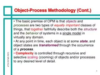
Objects and Processes • Objects and processes are two types of equally important things (entities) required to describe a system in a single, unifying model • At any point in time, each object is at some state. • Object states are transformed through the occurrence of a process • Complexity is controlled through recursive and selective scaling (zooming) of objects and/or processes to any desired level of details
Unified Modeling Language (UML) – Overview • Merger of Booch, Rumbaugh, and Jacobson’s earlier methods • Emphasis on notation, less on semantics • Recognized in 1997 as OMG standard • UML has multiple-views • Each view specifies a different aspect • The diagram types are divided into: • Structural diagrams • Procedural diagrams
State Diagrams State Diagrams Class Diagrams Use Case Diagrams Use Case Diagrams State Diagrams Use Case Diagrams State Diagrams Use Case Diagrams Object Diagrams Use Case Diagrams Sequence Diagrams Scenario Diagrams State Diagrams Scenario Diagrams State Diagrams Component Diagrams Collaboration Diagrams Models Component Diagrams Scenario Diagrams Component Diagrams Scenario Diagrams Deployment Diagrams Statechart Diagrams Activity Diagrams UML Diagram Types (views) • Structural diagrams • Procedural diagrams
OPM vs. UML • Behavior of the system can be spread across five diagram types • System’s structure and behavior are specified at different and separate views • Need to validate consistency among the various views • Process is an entity that uniformly represents patterns of behavior • System’s structure and behavior are specified side-by-side, enabling one to see the whole picture in a single view • No need for mental transformations and integration across different views
Experimenting with OPM and UML in the Web Applications Domain • The subjects: 3rd year students at the Technion • The experiment took place during the final examination of the course “Specification and Analysis of IS” (spring, 2002) • The groups were found to be identical (t = –0.19, p < 0.85)
Sample of Experiment Questions • Does the structure of the system support the following query: "who is the customer that ordered a specific product?" Explain. • What is the trigger of project order handling? From which diagram did you conclude it? • Is it possible that only the advance (10%) of a project, of which 50% had been completed was paid? Explain. • Add to the model a possibility to view a report of all the projects which 50% of their assignments were completed, but the projects have not supplied yet.
OPM vs. UML - Experiment Conclusions The single type of diagram in OPM, the OPD, is easier to understand and apply by untrained users. UML’s segregation of the system model into multiple views is a major source of difficulty in capturing the system as a whole and being able to coherently follow the functionality it performs
OPM’s Generic Code Generator - OPM-GCG • OPM-GCG is an important component of Object-Process Case Tool (OPCAT), a fully Integrated Systems Engineering Environment (http://www.objectprocess.org) • OPM-GCG uses Object-Process Language (OPL) as a XML infrastructure for implementation generation
OPM-GCG Components • OPCAT TIP (Template for Implementation Programming) - enables offline insertion and updating of translation rules from OPL templates to various (programming and other) languages • Implementation Generator - uses the corresponding translation rules along with the system OPL-XML script in order to create the system implementation in a specific target language
OPM-GCG User Interface <xs:element name="ObjectExhibitionSentence"> <xs:complexType> <xs:sequence> <xs:element name = "ObjectName" type="xs:string"/> <xs:element ref="ExhibitedObject" minOccurs="0“ maxOccurs="unbounded"/> <xs:element name = "Operation" type="xs:string" minOccurs="0" maxOccurs="unbounded"/> </xs:sequence> </xs:complexType> </xs:element>
OPM-GCG – A Simple Example Sample of the OPL Script Order can be ordered, paid, or supplied. Ordered is initial.Supplied is final. Orderis owned by Customer. Order relates to Product. Product exhibits Quantity.Quantity is of type integer. User is environmental and physical. User handles Product Handling. Product Handling affects Customer and Product. Product Handling yields Order. Product Handling yields either Receipt or No Product Message.
The Java Code Generated for the class Order public Customer gettheisownedbyCustomer() { return theisownedbyCustomer; } public void settheisownedbyCustomer (Customer newisownedbyCustomer) { theisownedbyCustomer= newisownedbyCustomer; } public Product gettherelatestoProduct() { return therelatestoProduct; } public void settherelatestoProduct (Product newrelatestoProduct) { therelatestoProduct= newrelatestoProduct; } } // File Order.java package OrderSystem; import opmTypes.*; public class Order extends opmObject { opmStatus theStatus; Customer theisownedbyCustomer; Product therelatestoProduct; public Order () { theStatus = new opmStatus(); initializeStatus(); } public void initializeStatus () { theStatus.addState (new opmState( "ordered", true, false, true)); theStatus.addState(new opmState( "paid", true, false, false)); theStatus.addState(new opmState( "supplied", false, true, false)); theStatus.addState(new opmState( "cancelled", false, true, false)); }
The Java Code Generated for Product Handling InventoryChecking theInventoryChecking = new InventoryChecking(); theInventoryChecking.run( new Integer( theProduct.gettheProductQuantity()), theInventoryEmpty); OrderPayingAndSupplying theOrderPayingAndSupplying = new OrderPayingAndSupplying(); theOrderPayingAndSupplying.run( theInventoryEmpty, theOrder, theProduct, theReceipt); } } public boolean gettheInventoryEmpty() { return theInventoryEmpty.booleanValue(); } public void settheInventoryEmpty(boolean newInventoryEmpty) { theInventoryEmpty= new Boolean (newInventoryEmpty); } } // File ProductHandling.java package OrderSystem; import opmTypes.*; public class ProductHandling extends opmProcess { Boolean theInventoryEmpty; public ProductHandling () { theInventoryEmpty=new Boolean(false); } public boolean preConditionHolds () { boolean check = true; if (check) { } return check; } public void run (Customer theCustomer, Product theProduct, Order theOrder, Receipt theReceipt) { if (preConditionHolds ()) { // Effect theCustomer // Effect theProduct theOrder = new Order(); theReceipt = new Receipt(); ProductOrdering theProductOrdering = new ProductOrdering(); theProductOrdering.run( theCustomer, theOrder);
OPM-GCG vs. Rhapsody by I-Logix • Rhapsody by I-Logix is a leading UML CASE tool • Rhapsody divides UML views into constructive and non-constructive ones • Class and Statecharts diagrams are considered constructive • Interaction diagrams are only partially constructive • Rhapsody uses them to define objects, operations, and messages;
OPM-GCG vs. Rhapsody by I-Logix • the bodies of the operations must be modeled in Statecharts or hand-coded in a browser. • Use case and activity diagrams are non-constructive; they only help analyze and document the system • Rhapsody defines translation rules only for the constructive UML views • Rhapsody uses a library of over 30 Java classes • Only some of them can be mapped to UML concepts.
The code Rhapsody generated • For the Ordering system, Rhapsody generated nine classes: System, Customer, Order, Product, Receipt, User, NoProductMessage, OrderPaying_, and OrderSupplying_ • Size-wise, • OPM-CGC code generated for the ordering system contains 265 lines, compared with • The corresponding Rhapsody code was • 739 lines
The code Rhapsody generated • Having 3 times less code to study, inspect, and modify is certainly an advantage • OPM-GCG generated code to all the stand-alone processes specified for the simple ordering system, • Rhapsody generated code only for the functionality expressed in the Statecharts
Summary • The differences between OPM and UML are underlined during the analysis and design stages: • UML is a multiple-view, object-oriented modeling language • OPM supports a single unifying bi-modal, structure-behavior view
Summary • OPM-GCG enablesthe generation of potentially complete application logic rather than just skeleton code • The translation rules of OPM-GCG are defined offline and can be dynamically changed • The consistency of OPM models is completely and faithfully reflected in the resulting code, eliminating the analysis-design-code gap
Ongoing and Future Work • Empirical evaluation of the quality and completeness of the code produced by: • OPM-GCG • Rhapsody • Extreme Programming (XP) • Checking the comprehensive and completeness of OPM-GCG-generated code for large systems