Download
1 / 32
320 likes | 417 Vues
Learn about a switch-tagged routing strategy for PC clusters with VLAN Ethernet, optimizing network performance and reducing broadcast storms. Explore fixed and minimal path assignment methods within the VLAN framework.

E N D
A Switch-Tagged Routing Methodology for PC Clusters with VLAN Ethernet • Author: MichihiroKoibuchi, Tomohiro Otsuka, Tomohiro Kudoh, HideharuAmano • Publisher: 2011 IEEE TRANSACTIONS ON PARALLEL AND DISTRIBUTED SYSTEMS • Presenter: Yuen-Shuo Li • Date: 2013/05/29
Introduction • High-throughput commercial Ethernet switches are now available,and the link bandwidth of Ethernet has rapidly increased • The standardizations of 10-gigabit Ethernet(10 GbE). • As of November 2008, GbEs were employed asinterconnects on 56 percent of the TOP500 supercomputers • Recent PC clusterswith Ethernet employ system software that supports lowlatencyzero- or one-copy communication used in systemarea networks (SANs)
Introduction(Cont.) • When developing a PC cluster using Ethernet, there are two ways of constructing an intracluster Ethernet. • To use a switch with several hundreds or more ports. • to connect a number of switches, each having dozens or ports. • Unlike clusters employing SANs, most current PC clusters using Ethernet have employed simple tree-based topologies. • This is mainly because topologies that include loops are not allowed in order to avoid broadcast storms which circulate packets forever in layer-2 Ethernet. too expensive!
Introduction(Cont.) • Broadcast Storms FF:FF:FF:FF:FF:FF domain: 10.1.1.10 broadcast: 10.1.1.255
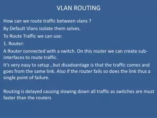
Introduction(Cont.) • The existing VLAN-based routing method cannot be easily applied to most current PC clusters with Ethernet. • The message passing interface(MPI) communication libraries used in such PC clusters usually do not support tagged VLAN technology. • Although the IEEE 802.1Q VLAN tag field can identify 4094 VLANs, commercial cost-effective Ehternet switches support only a limited number of VLANs.
Introduction(Cont.) • But STP and RSTP are not aware of VLAN • When STP was developed, the concept of a VLAN had not even entered anyone’s thoughts. • When these protocols are enabled, all links out of a spanning tree are automatically disabled. • The MSTP and PVST are STPs which support VLANs. They are quite useful for the VLAN-based routing implementation. • however, there are only a few cost-effective Ethernet switches that support these protocols.
Introduction(Cont.) • Virtual LAN, a network of computers that behave as if they are connected to the same wire even though they may actually be physically located on different segments of a LAN. VLANs are configured through software rather than hardware, which makes them extremely flexible. 802.1Q does not actually encapsulate the original frame. Instead, for Ethernet frames, it adds a 32-bit field between the source MAC address and the EtherType/Length fields of the original frame.
Introduction(Cont.) • VLAN technology was not intended for increasing network throughput, but for partitioning hosts into multiple groups.
Introduction(Cont.) • The existing VLAN-based routing implementation often requires a complicated VLAN configuration at each host. • STP and RSTP are not aware of VLANs • Most Ethernet switches support IEEE 820.1D STP or 802.1D-2004 Rapid STP(RSTP) to prevent loops in a network. • MSTP and PVST are STPs which support VLANs. However, there are currently only a few cost-effective Ethernet switches that support these protocols.
Introduction(Cont.) • Spanning Tree Protocol(STP) • Using the spanning tree algorithm, STP provides path redundancy while preventing undesirable loops in a network that are created by multiple active paths between stations. Root Bridge
SWITCH-TAGGED ROUTING METHODOLOGY • MPI communication libraries do not need to use tagged VLAN technology • It simply configures a switch • It disables the spanning-tree protocol (STP), • allocates the VLAN sets • optionally registers static MAC addresses of hosts for the routing.
Frame Tagging at Switch • A switch behavior of the VLAN tagging operation • When an untagged frame enters a port, it is tagged with a default VLAN ID tag number (port VLAN ID, PVID). • Frames leaving the switch are either tagged or untagged depending on the port’s VLAN configuration. • If the port is a “tagged” member of a VLAN, the output frame is tagged with the respective VLAN ID. • If the port is an “untagged” member of a VLAN, the output frame is left untagged.
SWITCH-TAGGED ROUTING METHODOLOGY • There are two switch-tagged strategies • Fixed VLAN Assignment • [8] VLAN-Based Minimal Paths in PC Cluster with Ethernet on Mesh and Torus • Renamed VLAN Assignment
Renamed VLAN assignment(Cont.) • Each switch that has p ports is configured according to the following procedure: • Let the PVID of port i be VLAN vi, and register the port in vi as an “untagged” member. Let i be zero. • Register each output port to which frames from the input port i can be routed in vi as an “untagged” member in order to implement paths. • if i < p – 1, let i=i+1 and go to step 2 • Combine two or more VLANs whose member ports are the same into a single VLAN in order to remove the duplication.
Renamed VLAN assignment(Cont.) • MAC Address Management at switches • Ethernet switches usually learn unknown MAC addresses when they receive frames. • When a path from host A to B and one from B to A use different VLANs, the intermediate switches of both paths cannot learn the destination MAC address. • This is because the MAC address self-learning procedure is independently performed on each VLAN. ?
Renamed VLAN assignment(Cont.) • This problem can be resolved through static MAC address registration. • Ethernet switches statically register pairs of MAC addresses, VLAN IDs, and output port numbers. • However, static registration cannot use the convenient switch function of address self-learning • We propose the following learning procedure in the case of fixed VLAN assignment. • For each VLAN, make a corresponding virtual interface on each host. In Linux operating systems, virtual interfaces can be made by using the “vconfig” command. • Give an IP address to each virtual interface at all hosts so that the interface has a unique network address that belongs to a different segment on the physical interface. • At each host, broadcast an ICMP or UDP message from each virtual interface so that switches learn the MAC address of the host in each VLAN
Renamed VLAN assignment(Cont.) • Breaking Cyclic Channel Dependencies • Renamed VLAN assignment introduces the possibility of broadcast storms among different VLANs when a switch receives frames whose destination MAC addresses are unknown, or when a broadcast occurs. • In addition, a combination of VLANs could cause deadlocks, because VLANs have to share network resources. • A renamed VLAN assignment with a deadlock-free routing algorithm does not cause broadcast storms. • Deterministic deadlock-free routing algorithms break cyclic channel dependency, and the channel dependency is implemented by the combination of VLANs. Thus, when a broadcast occurs, frames never arrive at a port of a switch they have already visited.
Renamed VLAN assignment • On/Off and Multispeed Link Regulation for Saving Power • The power consumption of links can be reduced by using the port-shutdown operation available in most commercial Ethernet switches. • Their operation was not originally intended to reduce power consumption; it is normally used to block the injection of unexpected frames from neighboring switches. • Standard management information base (MIB) + simple network management protocol (SNMP). • All except ports: • The power consumption of switches when all the ports are shutdown • Max (port ratio): • The power consumption when all ports are activated with 1 Gbps. Power Consumption of GbE Switches (W)
Limitation of Existing Commodity Switches • Applicable Commercial Switches • Commodity GbE switches cost from under 100 dollars to 10,000 dollars. The cheapest switches do not support VLAN technology, or few functions of VLANs, and hence, they cannot employ our methodology. • Upper Limit on Number of Hosts • The number of hosts is limited to size of the MAC address table in Ethernet switches. Each entry of an MAC address table consists of the destination MAC address, VLAN ID, and port.
Overhead of VLAN Operations U: Untagged T: Tagged
Overhead of On/Off and Multispeed Link • The overhead of Ethernet switches varies depending on the services provided by the commercial products. For example, some switches have unique functions for setting up the port, such as port mirroring for traffic monitoring, that would affect the overhead.
` • In this monitor, first, we used topology B, and hosts 0, 1, 2, and 3 sent to 2, 3, 0, and 1 with a highest injection rate using Tperf [24], respectively. After 5 seconds, host 3 sends data to 2 with a highest injection rate, and the topology is updated to topology A by reactivating the link. After 10 seconds, the data transfer from host 0 to 2 is terminated, and the topology is changed to topology B by deactivating the link. UDP TCP
Evaluation Using PC Clusters We evaluated the effect of the IEEE 802.3x link-level flow control. FC None: the link-level flow control is disabled FC All: the flow control is enable at every link
Misc Cluster • a 66-host cluster using six GbE switches(Dell PowerConnect 6248, 48 ports) • Each switch in the Misc cluster connects to 11 hosts. • SuperNova • a 225-host PC cluster using the eight same GbE switches. • Each switch in SuperNova cluster connects to 28 or 29 hosts.
We constructed both of indirect topologies (fat tree and Myrinet-clos)
Collective communication is frequently used in parallel programming using MPI.
The number of processes for parallel execution was fixed to 16 in the case of the PC-cluster testbed, while the SuperNovacluster used 128 processes in CG, FT, IS, LU, and MG and 225 processes (the maximum size) in SP and BT. “Tree (6link)” stands for the tree topology that uses six links between switches using link aggregation
CONCLUSIONS • Proposed a switch-tagged routing methodology • Implement the routing algorithms on PC clusters with Ethernet • Simple host configuration and high portability • Evaluation results • NAS parallel benchmarks performance comparable to that of an ideal 1-switch (full crossbar) network, • The torus topology achieves up to a 27 percent performance improvement compared with the tree topology using link aggregation. • The on/off and multispeed link regulation reduces the power consumption of switches by up to 25 percent