Download
1 / 10
100 likes | 224 Vues
This chapter delves into the instrumental resolution variance in Small-Angle Neutron Scattering (SANS) focusing on key parameters such as geometry, wavelength spread, and gravitational influence. It makes a crucial distinction between high and low flux configurations impacting the resolution, detailing how scattering peaks broaden at high Q-values. The chapter presents a comprehensive analysis using a specific instrument configuration with clarifications on associated measurements like source-to-sample and sample-to-detector distances. Ultimately, it highlights the trade-offs between flux and resolution in SANS experiments.

E N D
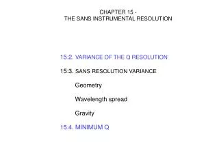
CHAPTER 15 - THE SANS INSTRUMENTAL RESOLUTION 15:2. VARIANCE OF THE Q RESOLUTION 15:3. SANS RESOLUTION VARIANCE Geometry Wavelength spread Gravity 15:4. MINIMUM Q
y z x 15:2. VARIANCE OF THE Q RESOLUTION Scattering variable: Variance of the Q resolution: neutron beam
2D area detector circular source aperture y circular sample aperture R1 R2 x L1 L2 y 2D area detector Dl l-Dl l+Dl l 2 Dl R1 r f x r cos(f) 15:3. SANS RESOLUTION VARIANCE Geometry Wavelength spread
source aperture sample aperture 2D area detector y v0 z L1 L2 PARABOLIC NEUTRON TRAJECTORIES millimeters meters
DERIVATIONS source sample detector horizontal vertical
SUMMARY geometry wavelength spread gravity R1: source aperture radius R2: sample aperture radius Dx3 and Dy3: sides of the detector cell L1: source-to-sample distance L2: sample-to-detector distance Dl: wavelength spread, FWHM of triangular distribution function
SPECIFIC INSTRUMENT CONFIGURATION L1 = 16.14 m, L2 = 13.19 m R1 = 0.715 cm, R2 = 0.635 cm Dx3 = Dy3 = 0.5 cm l = 6 Å, Dl/l = 0.13.
2D area detector source aperture sample aperture L1 L2 15:4. MINIMUM Q umbra penumbra geometry gravity
COMMENTS -- There is always a trade-off between flux-on-sample and instrumental resolution. -- High flux and low resolution condition is obtained for the high-Q instrument configuration. Low flux and high resolution condition is obtained for the low-Q instrument resolution. -- The variance of the Q resolution increases with Q. Scattering peaks broaden a lot at high-Q. Higher order peaks are hard to resolve.