RF studies at Fermilab MuCool Test Area
10 likes | 164 Vues
Molybdenum buttons. RF studies at Fermilab MuCool Test Area. Dazhang Huang, Yagmur Torun, Illinois Institute of Technology Alan Bross, Alfred Moretti, Zubao Qian, Fermi National Accelerator Laboratory James Norem, Argonne National Laboratory

RF studies at Fermilab MuCool Test Area
E N D
Presentation Transcript
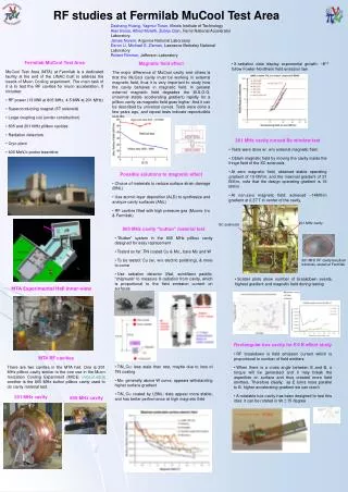
Molybdenum buttons RF studies at Fermilab MuCool Test Area Dazhang Huang, Yagmur Torun, Illinois Institute of Technology Alan Bross, Alfred Moretti, Zubao Qian, Fermi National Accelerator Laboratory James Norem, Argonne National Laboratory Derun Li, Michael S. Zisman, Lawrence Berkeley National Laboratory Robert Rimmer, Jefferson Laboratory • Fermilab MuCool Test Area • MuCool Test Area (MTA) at Fermilab is a dedicated facility at the end of the LINAC built to address the needs of Muon Cooling experiment. The main task of it is to test the RF cavities for muon acceleration. It includes: • RF power (13 MW at 805 MHz, 4.5 MW at 201 MHz) • Superconducting magnet (5T solenoid) • Large coupling coil (under construction) • 805 and 201 MHz pillbox cavities • Radiation detectors • Cryo plant • 400 MeV/c proton beamline Magnetic field effect The major difference of MuCool cavity and others is that the MuCool cavity must be working in external magnetic field, thus it is very important to study how the cavity behaves in magnetic field. In general external magnetic field degrades the M.S.O.G. (maximal stable accelerating gradient) rapidly for a pillbox cavity as magnetic field goes higher. And it can be described by universal curves. Tests were done a few years ago, and repeat tests indicate reproducible results • X-radiation data display exponential growth: ~E13, follow Fowler-Nordheim field emission law • 201 MHz cavity curved Be window test • Tests were done w/. w/o external magnetic field. • Obtain magnetic field by moving the cavity inside the fringe field of the SC solenoids • At zero magnetic field, obtained stable operating gradient of 19 MV/m, and the maximal gradient of 21 MV/m, note that the design operating gradient is 16 MV/m • At non-zero magnetic field: achieved ~14MV/m gradient at 0,37 T in center of the cavity. • Possible solutions to magnetic effect • Choice of materials to reduce surface strain damage (BNL) • Use atomic layer deposition (ALD) to synthesize and analyze cavity surfaces (ANL) • RF cavities filled with high pressure gas (Muons. Inc & Fermilab) 201 MHz cavity SC solenoids • 805 MHz cavity “button” material test • “Button” system in the 805 MHz pillbox cavity designed for easy replacement • Tested so far: TiN coated Cu & Mo., bare Mo and W • To be tested: Cu (w/, w/o electric polishing), & more to come • Use radiation detector (NaI, scintillator paddle, “chipmunk” to measure X-radiation from cavity, which is proportional to the field emission current on surfaces 201 MHz RF cavity beryllium windows, tested at Fermilab • Scatter plots show number of breakdown events, highest gradient and magnetic field during testing MTA Experimental Hall inner-view • Rectangular box cavity for EB effect study • RF breakdown is field emission current which is proportional to number of field emitters • When there is a cross angle between E and B, a torque will be generated and it may break the asperities on surface and thus created more field emitters. Therefore ideally, as E turns more parallel to B, higher accelerating gradient we can reach • A rotatable box cavity has been designed to test this idea: it can be rotated in 90±15 degree MTA RF cavities There are two cavities in the MTA hall. One is 201 MHz pillbox cavity similar to the one use in the Muon Ionization Cooling Experiment (MICE: mice.iit.edu); another is the 805 MHz button pillbox cavity used to do cavity material test. • TiN_Cu: less stale than rest, maybe due to loss of TiN coating • Mo: generally above W curve, appears withstanding higher surface gradient • TiN_Cu coated by LBNL: data appear more stable, and has better performance at high magnetic field π seen in the Cherenkov Detector April 2nd 2008 201 MHz cavity 805 MHz cavity